5-30
3550 LCR Meter Instruction Manual Programming and Interfacing
The GPIB Interface
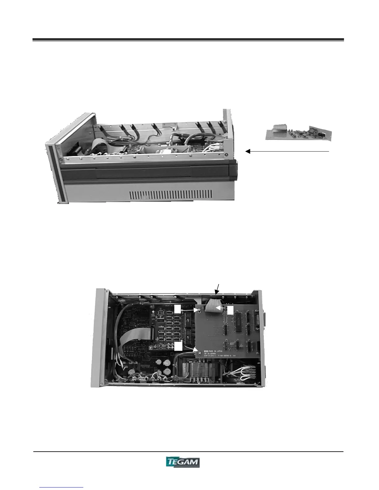
Installation of the GPIB Board, Option #3505 cont’d:
Figure 5.4b – Side View
4. Then, connect the cable “6” of the GPIB board with the connector of the Control Board “5”.
5. Match the 2 holes (“7” and “8”) to the "pillars" on the Control Board, and tighten the
screws.
Figure 5.4c – Top View
6. Replace the top cover.
NOTE: The input and output commands & formats for GPIB are the same as they are for RS232C.
Refer to the previous section on RS-232C communications for details regarding specific commands
and formats.
5
8
6
7
Slide the GPIB card into the
slot and tighten screws “3”
and “4” .