5-6
3550 LCR Meter Instruction Manual Programming and Interfacing
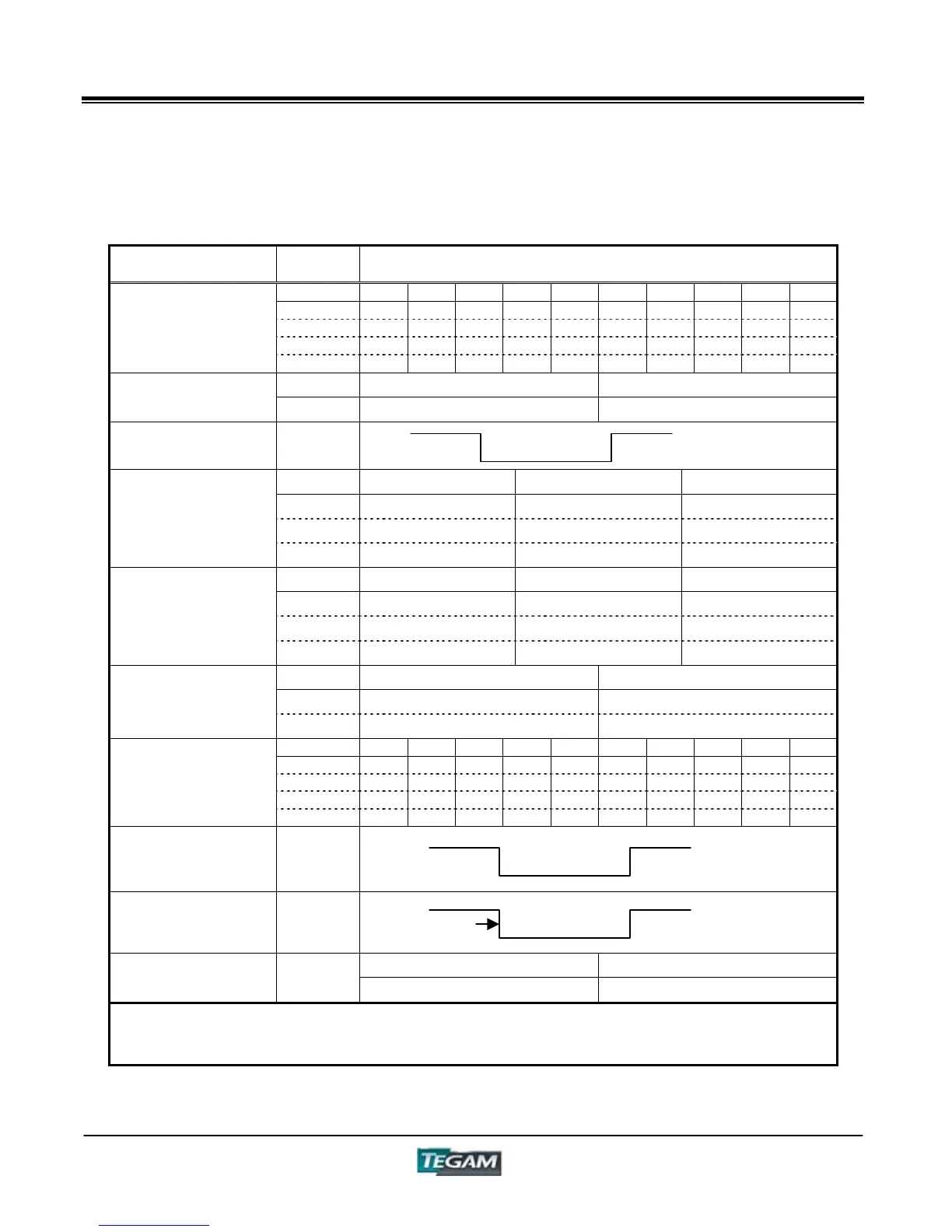
Control I/O Connector cont’d:
Table 5.2 - Control I/O Function Summary
Item PIN No. Functions
0 1 2 3 4 5 6 7 8 9
5, 30 0 0 0 0 0 0 0 0 1 1
6, 31 0 0 0 0 1 1 1 1 0 0
7, 32 0 0 1 1 0 0 1 1 0 0
*PANEL
8, 33 0 1 0 1 0 1 0 1 0 1
EXT PANEL
*CONTROL
PANEL/EXT
3, 28
ON OFF
*EXTERNAL TRIGGER
4, 29
Low NG High NG GO
14
0 1 1
13
1 0 1
DISPLAY A
GO/NO-GO
15
1 1 0
Low NG High NG GO
39
0 1 1
38
1 0 1
DISPLAY B
GO/NO-GO
40
1 1 0
GO NO-GO
16
0 1
TOTAL
GO/NO-GO
41
1 0
0 1 2 3 4 5 6 7 8 9
17
1 1 1 1 1 1 1 1 0 0
42
1 1 1 1 0 0 0 0 1 1
18
1 1 0 0 1 1 0 0 1 1
BIN No.
43
1 0 1 0 1 0 1 0 1 0
TEST BUSY 19
MEASURE
END
44
ON OFF
**ERROR
20
0 1
*: Input Pin
**: The ERROR signal indicates a GO/NO-GO decision error. When the range is wrong, or the fixed
current/voltage setting value has not been reached, "0" is outputted.
"1" for the Output Pins = C-E Open, "0" = C-E Short
OFF
ON (5~15ms)
OFF
READY (OFF) BUSY (ON)
Test End ON (1ms)