5-2
3550 LCR Meter Instruction Manual Programming and Interfacing
Interfacing to the 3550
This section provides detailed information about the 3550 electrical interfaces and their
functionality. It will provide all of the necessary information required to integrate the 3550 easily
into a working test application. A Control I/O connector is available for optically coupled TTL
interface to PLCs and other control hardware. The 3550 has a standard RS232 communications
port and an optional GPIB interface for software-based applications.
Control I/O Connector
Located on the rear panel, the Control I/O Connector offers an optically isolated, TTL-level
interface for integration into PLC and other hardware controlled applications.
These terminals require a positive 5V~24V signal across the 3~8 Pins (these are the anode
connections for external trigger, panel enable/disable, and the four panel BCD inputs) and a
common potential across pins 28~33. A constant current diode is in series with the 5~24V supply
to limit the current flowing through the photo diode. There is no need for a current limiting resistor
for the inputs or outputs of the Control I/O Connector.
Inputs
There are 3 groups of inputs available from the Control I/O Connector:
CONTROL PANEL/EXT (Pins 3 & 28) – This input works in conjunction with the front panel
trigger or the rear panel External Trigger Input. When this input is true (current flows
through pins 3 & 28) the rear panel External Trigger is enabled. If the Control PANEL/EXT
input is false, then the triggering must be performed from the front panel.
External Trigger (Pins 4 & 29) – Used with the CONTROL PANEL/EXT input. The 3550 will
take measurements when the CONTROL PANEL/EXT input AND
External Trigger are true.
Panel BCD Inputs, [Pins 5~8 (Anode) and Pins 30~33 (Cathode)]. - A BCD setting of 0~9 is
required. Settings other than 0~9 will automatically default to panel 9.
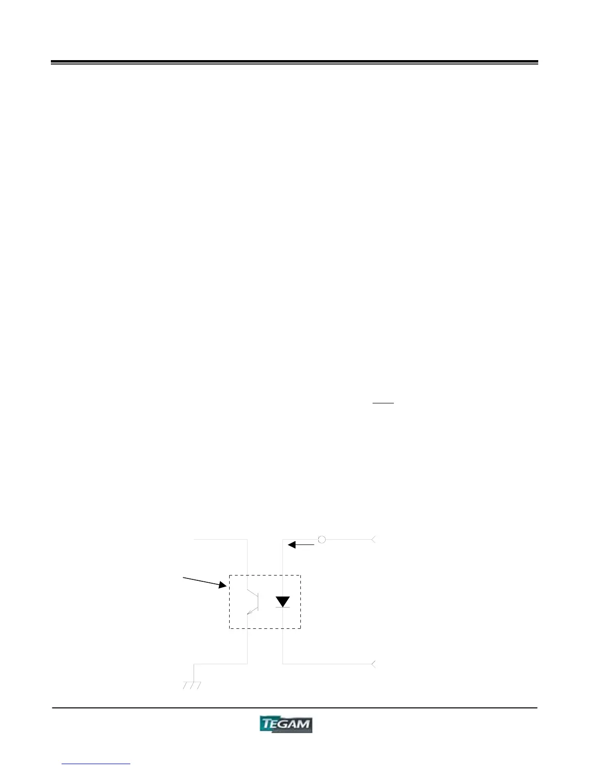
The inputs of the Control I/O Connector are optically Isolated. The figure below is a representation
of a typical input.
Figure 5.1 – Input Schematic
Photo
Coupler
Fixed Current
Diode
3~8
28~33
10 mA