5-5
3550 LCR Meter Instruction Manual Programming and Interfacing
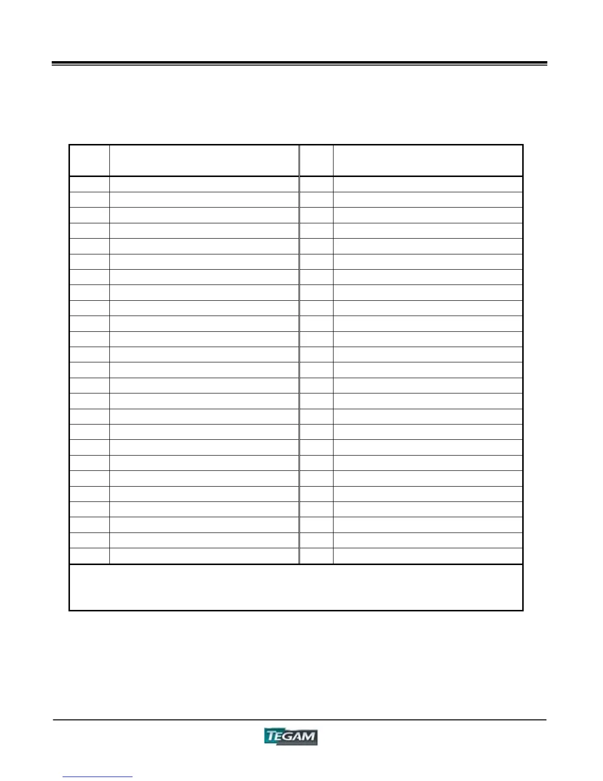
Control I/O Connector cont’d:
Table 5.1 - Connector Pin Designations
PIN
NO.
Signal Name
PIN
NO.
Signal Name
1 EXT POWER 26 EXT POWER
2 EMITTER COMMON 27 EMITTER COMMON
3* CONTROL PANEL/EXT (A) 28* CONTROL PANEL/EXT (K)
4* EXTERNAL TRIGGER (A) 29* EXTERNAL TRIGGER (K)
5* PANEL 2
3
(A) 30* PANEL 2
3
(K)
6* PANEL 2
2
(A) 31* PANEL 2
2
(K)
7* PANEL 2
1
(A) 32* PANEL 2
1
(K)
8* PANEL 2
0
(A) 33* PANEL 2
0
(K)
9 34
10 35
11 36
12 37
13 DISPLAY A HNG 38 DISPLAY B HNG
14 DISPLAY A LNG 39 DISPLAY B LNG
15 DISPLAY A GO 40 DISPLAY B GO
16 TOTAL GO 41 TOTAL NG
17 BIN 2
3
42 BIN 2
2
18 BIN 2
1
43 BIN 2
0
19 TEST BUSY 44 MEASURE END
20 ERROR 45
21 46
22 47
23 48
24 49
25 50
* : Input Pin
(A) and (K) are the Anode(A) and Cathode(K) of the photo coupler LED
Output is the Open Collector of the transistor of the photo coupler