4-5
Model 3550 LCR Meter Instruction Manual Operating Instructions
Measurement Tips cont’d:
Test Lead Requirements
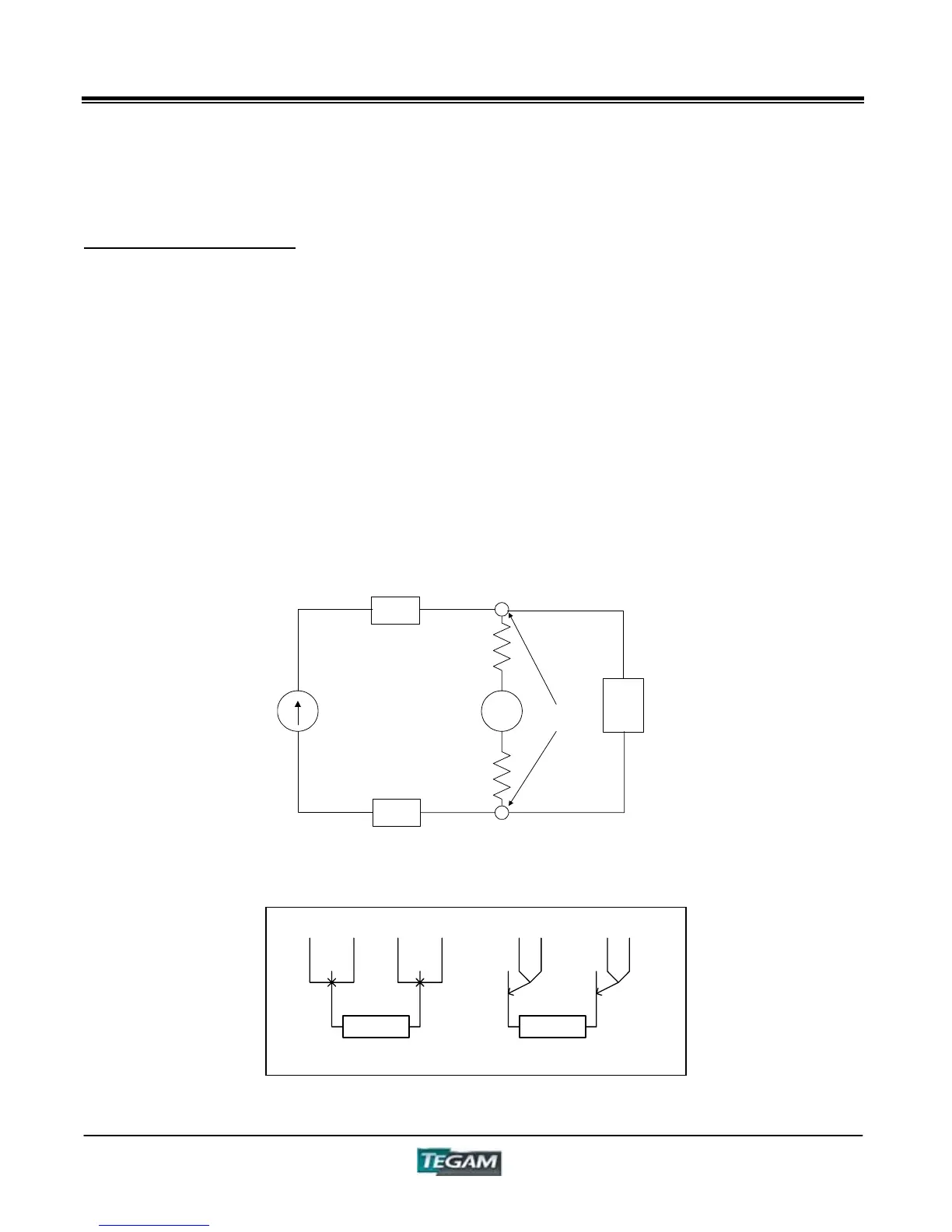
Four-wire Kelvin-type cables or fixtures must be used with the 3550 in order to obtain accurate
impedance measurements. The Kelvin measurement technique allows significant accuracy
advantage over the two-wire method. This is because it virtually eliminates lead resistance and
inductance and reduces stray capacitance between the source and sense leads.
Two of the four conductors are designated as source leads. These source leads provide the
precision test current that will be referenced in making the resistance measurement. Since current
is the same throughout a series circuit, the lead resistance of the test leads will not have any
effect on the level of reference current.
The other two conductors are designated as voltage sense leads. These leads originate from a high
impedance, volt measurement circuit. When these leads are terminated at the points of contact,
an exact resistance reading is calculated by the 3550’s microprocessor. The series lead resistance
of the voltage sense leads is negligible due to the high impedance of the voltage measurement
circuitry within the 3550.
Figure 4.1a: Four-Wire Kelvin Measurement
V
REFERENCE
CURRENT SOURCE
H
FORCE
/L
FORCE
VOLTAGE
SENSE
H
SENSE
/L
SENSE
CONTACT
POINTS
Z
S
Z
S
Z
DUT
Figure 4.1b: Proper Application of Four Wire Kelvin Measurement
DUT DUT
H
S
H
F
L
F
L
S
H
S
H
F
L
F
L
S
CORRECT INCORREC