4-22
Model 3550 LCR Meter Instruction Manual Operating Instructions
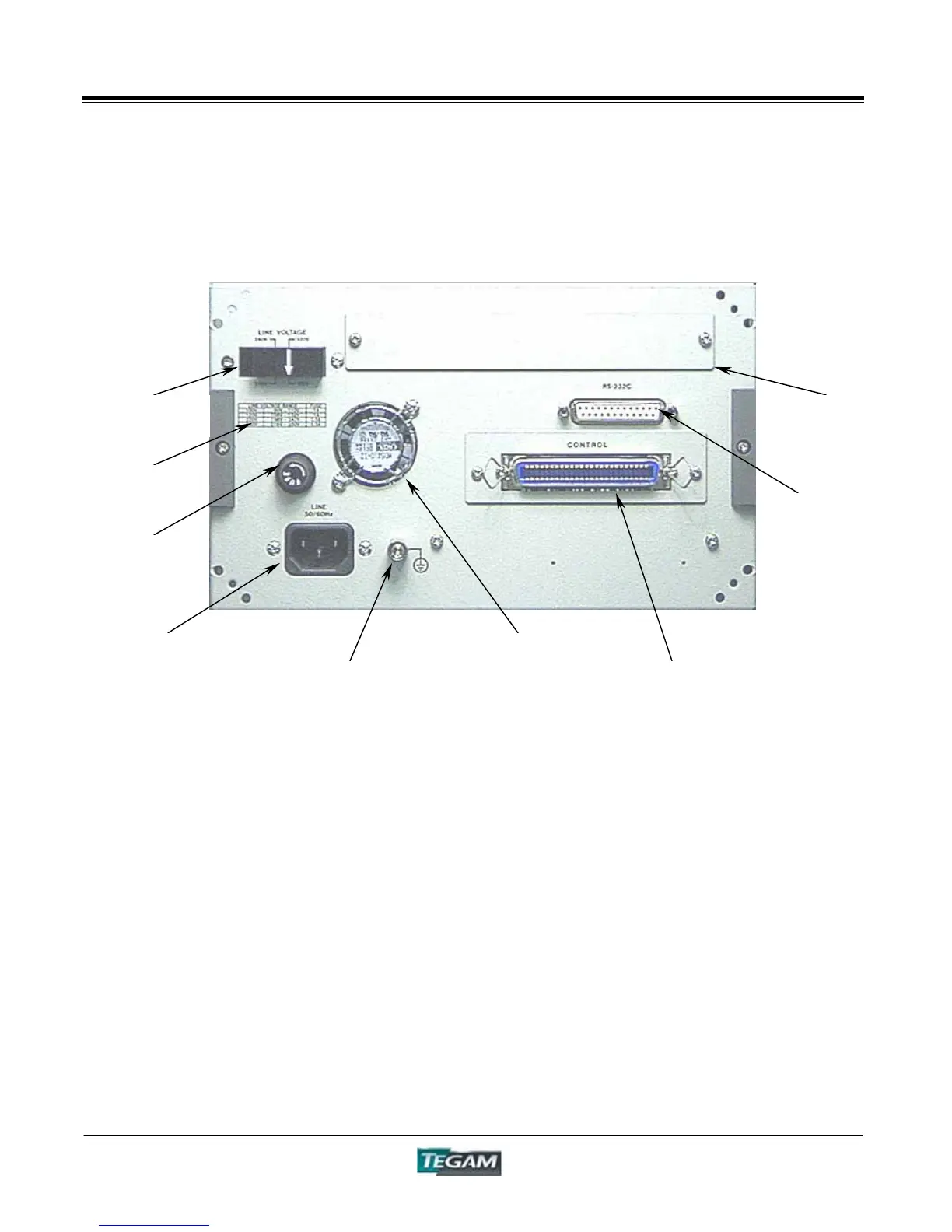
Rear Panel Description
Figure 4.3 - Rear Panel Layout
Line Voltage Selector Plug – The Model 3550 is
capable of 100/120/220/240 VAC 50/60 Hz Operation. To
change the line voltage, remove the plug by pulling it
from the rear panel. Put the plug back in to the socket
with the arrow pointing to one of four supply voltage
settings.
Fuse Input – Use 3AG Type Fuses, ¼” X 1¼”
(6.35X31.75mm)
Fuse Rating Chart - See Rear Panel or Preparation for
Use Section for fuse ampere ratings. Use fast acting fuses
only.
VAC Input – 100/120/220/240, power input. An internal
line filter is included in this input.
GND Terminal – The GND binding post provides a direct
connection to the instrument’s chassis and the grounded
connector of the VAC input plug.
Cooling Fan Ventilation Holes – To prevent
overheating, keep these ventilation holes free of
obstructions. Periodically inspect these holes to assure
they are free of obstructions.
Control I/O Port – The Control I/O Port has optically
isolated TTL inputs and outputs used for remote
operation. Inputs include BCD Panel Selection and trigger
inputs. Outputs include A, B and total Comparator
outputs, End of measurement, BIN, Busy and Error
Outputs. The control connector also includes pins for
external power connections.
RS-232C Port – Standard RS-232C Port.
GPIB Board Slot – Slot provided for factory installed
GPIB (IEEE-488.2) option PN# 3505.
GND Terminal
VAC Input
Fuse Input
Line Voltage
Selector Plug
GPIB Board
Slot
RS-232C Port
Control I/O
Port
Cooling Fan
Ventilation
Fuse Rating
Chart