4-3
Model 3550 LCR Meter Instruction Manual Operating Instructions
Measurement Tips cont’d:
Measurement Circuit Modes
When the Measurement Circuit Mode is set to "AUTO", the Parallel Mode (PRL) or the Serial Mode
(SER) is automatically selected by the instrument based on the Measurement Range. The
measurement range is determined by the instrument by the magnitude of |Z| with no regards to D
or Q of the DUT.
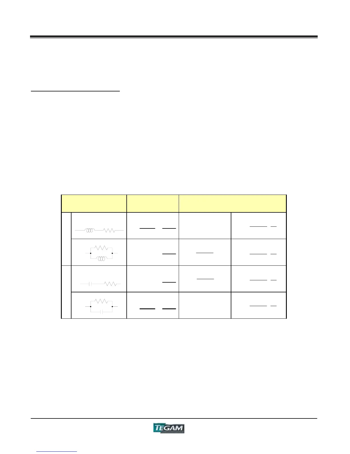
Thus, the measured values of a component will vary depending on whether series or parallel
equivalent circuit modes are used. The relationship between series and parallel equivalent circuit
measurements is illustrated in Table 4.1.
Table 4.1: Relationship Between Series and Parallel Equivalent Circuit Values
Equivalent Circuit
Mode
Dissipation
Factor: D
Conversion Formula
(SER)
D =
R
Z
L
S
=
1
Q
L
(PRL)
D =
Z
L
P
G
=
1
Q
(SER)
D =
Z
C
S
R
=
1
Q
C
(PRL)
D =
G
Z
C
P
=
1
Q
As a general rule, when measuring components where the reactive component is high, >10kƻ
then the parallel equivalent mode should be used as parallel leakage becomes more significant to
the measurement.
For low reactance components, <10ƻ the series equivalent mode should be used since lead
resistance becomes more significant to the reading than parallel leakage.
For measurements of component values that fall somewhere in between, follow the manufacturer’s
recommendations.
Ls
G
L
C
G
C
S
S
2
P LD1L
P
2
S L
D1
1
L
S
2
P C
D1
1
C
P
2
S CD1C
1
D1
D
G
2
2
G
1
D1
D
R
2
2
1
D1
D
G
2
2
G
1
D1
D
R
2
2