Model 3550 LCR Meter Instruction Manual Instrument Description
1-5
Performance Specifications
The advertised specifications of the model 3550 are valid under the following conditions:
1. The instrument must be verified and/or adjusted using the methods and intervals as
described in the calibration section of this user’s manual.
2. The instrument must be in an environment, which does not exceed the limitations as
defined under “Environmental” in the Miscellaneous Specifications section.
3. The unit is allowed to warm up for a period of at least 30 minutes before measurements
are taken. A warm-up period of 60 minutes is recommended after exposure to or storage in
a high humidity, (non-condensing), environment.
4. Only TEGAM-manufactured Kelvin Klips™, Tweezers and other test fixtures are used with
this device during measurements.
Measurement Parameters:
Inductance (L), Capacitance(C), Resistance(R), Impedance (|Z|), Admittance (|Y|),
Dissipation Factor (D), Quality (Q), Equivalent Series Resistance (R
S
), Equivalent Parallel
Resistance (R
P
), Conductance (G), Reactance (X), Susceptance (B), and Phase Angle (LJ).
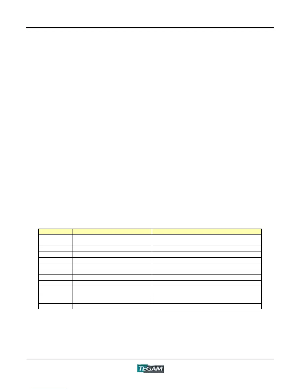
Measurement Ranges
Table 1.1 – Model 3550 Measurement Range Limits
Parameter Low Limit High Limit
L 320.0nH (At: 10ƻ 5MHz) 0.7500MH(At: 199.99Mƻ 42Hz) (LJ=90°)
C 0.160pF (At: 100kƻ 5MHz) 0.037F(At: 100mƻ 42Hz) (LJ=-90°)
R 0.01mƻ 199.99Mƻ
|Z| 0.01mƻ 199.99Mƻ
|Y| 5.000nS(199.99Mƻ) 100.00S(100mƻ)
D 0.0001 9.999
Q 0.1 1999.9
R
S
0.01mƻ 199.99Mƻ
R
P
0.01mƻ 199.99Mƻ
G 5.000nS(199.99Mƻ) 100.00S(100mƻ)
X 0.01mƻ 199.99Mƻ
B 5.000nS(199.99Mƻ) 100.00S(100mƻ)
LJ -180.00° 180.00°
NOTE: The Measurement Range is dependent on the Measurement Frequency. The figures in
parentheses are DUT impedance values.