Model 3550 LCR Meter Instruction Manual
Appendix
Setting the Constant Voltage Mode
To Enable the Constant Voltage Mode
1. Check and confirm that the [CV/CC] button is not illuminated.
2. Press the [V] button until Display C indicates voltage.
3. Press the [CV/CC] button.
4. Check and confirm that both the [CV/CC] and [V] button are illuminated.
The 3550 is now operating in Constant Voltage Mode.
Calculating the Maximum Allowable Constant Voltage Setting
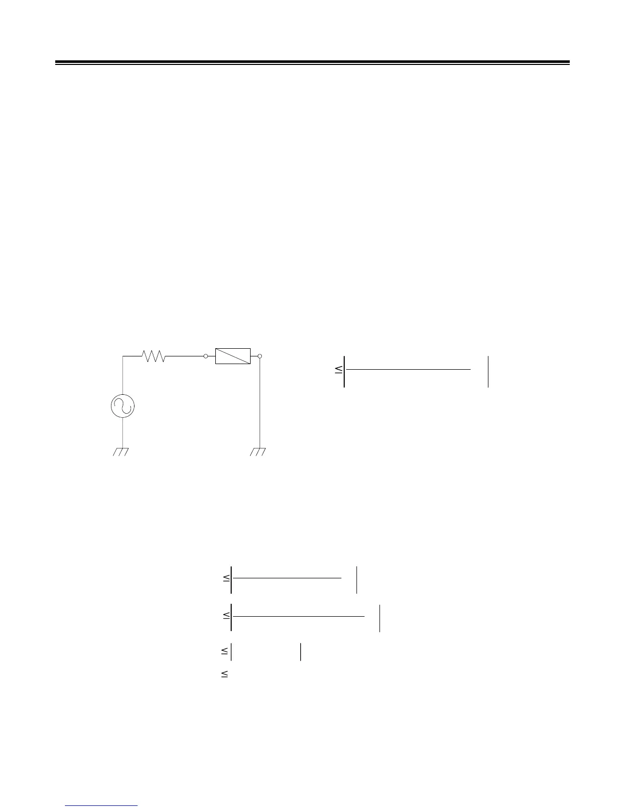
The figure bellow is an equivalent circuit of the Output Oscillator of the 3550. When connected to a
DUT of a known impedance, |Z| and known phase angle, theta; the constant voltage maximum
limit for a defined impedance and theta may be determined by using formula 1.
NOTE: The absolute maximum allowable constant voltage setting (regardless of DUT impedance)
is limited by instrument capability. This maximum amount is 3.58V.
DUT
|Z|
50
:
OSC
Z cos
T
+ jZ sin
T
50+( Z cos
T
+ jZ sin
T
xVCV
Formula 1
Where:
CV = Constant Voltage Setting Limit
V = Maximum Oscillator Voltage Setting
Sample Calculation:
For a test frequency of 1 kHz, |Z| = 100ƻ, and theta (LJ) =45º, the maximum constant voltage
setting is calculated as follows:
CV
Z cos
T
+ jZ sin
T
50+( Z cos
T
+ jZ sin
T
x5
CV
100cos
5º+ j100sin
º
50+(100cos45º + j100sin45º
x5
CV
3.458 + j0.903
CV
3.574V
A.3