4-29
Model 3550 LCR Meter Instruction Manual Operating Instructions
Making Accurate Measurements cont’d:
Equivalent Circuits cont’d
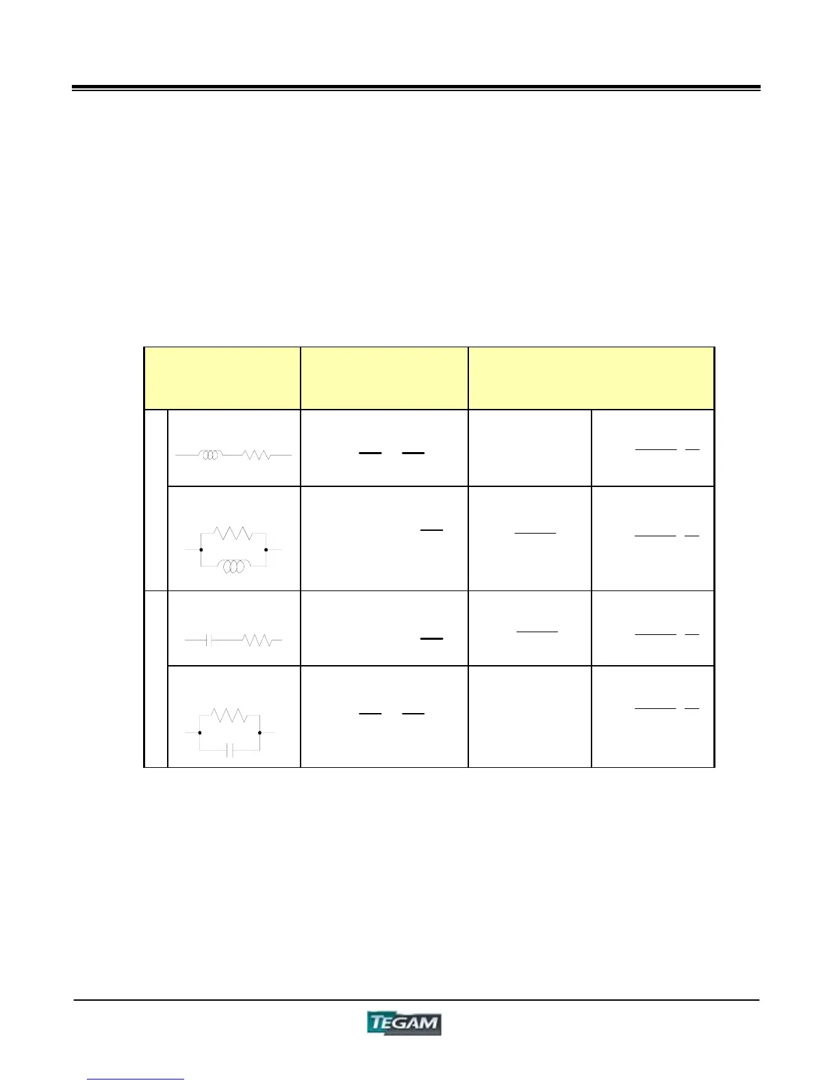
Table 4.7 Illustrates the effects of leakage and series resistance on component measurements. It
also provides some additional formulae to illustrate the relationship that dissipation factor has on a
device’s impedance measurement.
Table 4.7 – Equivalent Circuit Relationships
Equivalent
Circuit
Mode
Dissipation Factor
(D) Conversion Formula
(SER)
Ls R
D = =
R
Z
L
S
1
Q
L
(PRL)
L
P
G
D = =
Z
L
P
G
1
Q
(SER)
Cs R
D = =
Z
C
S
R
1
Q
C
(PRL)
C
P
G
D = =
G
Z
C
P
1
Q
The Series Equivalent Circuit Mode of the 3550 can be used for testing devices where series
impedance has a great effect on the measurement. Parallel Equivalent Circuit Mode is used for
testing devices with high reactance where parallel leakage becomes more significant. The formulae
in Table 4.7 can be used to convert readings in one equivalent circuit mode to the other.
Note that the measured value of D (or Q) will not be different whether it is measured in Series or
Parallel Equivalent circuit mode.
S
2
P LD1L
1
D1
D
G
2
2
P
2
S L
D1
1
L
G
1
D1
D
R
2
2
S
2
P C
D1
1
C
1
D1
D
G
2
2
P
2
S CD1C
G
1
D1
D
R
2
2