Model 3550 LCR Meter Instruction Manual Instrument Description
1-14
Formulas and Measurement Accuracy cont’d:
The 3550 calculates the various measurement values using the inter-terminal voltage (V) applied
to the DUT (device under test) terminals, the current (I) that occurs in relation to the voltage, the
Phase Angle (LJ) of (V) and (I), and the Angular Velocity (ǔ) of the measurement frequency.
These factors are used in the formulas below to determine values for the measurements made by
the TEGAM 3550.
Note: The Phase Angle is based on Impedance (Z). In order to base the Phase Angle on
Admittance (Y), add a "-" sign to the Impedance value to negate it.
Thus, ij for Admittance will be ij=-LJ.
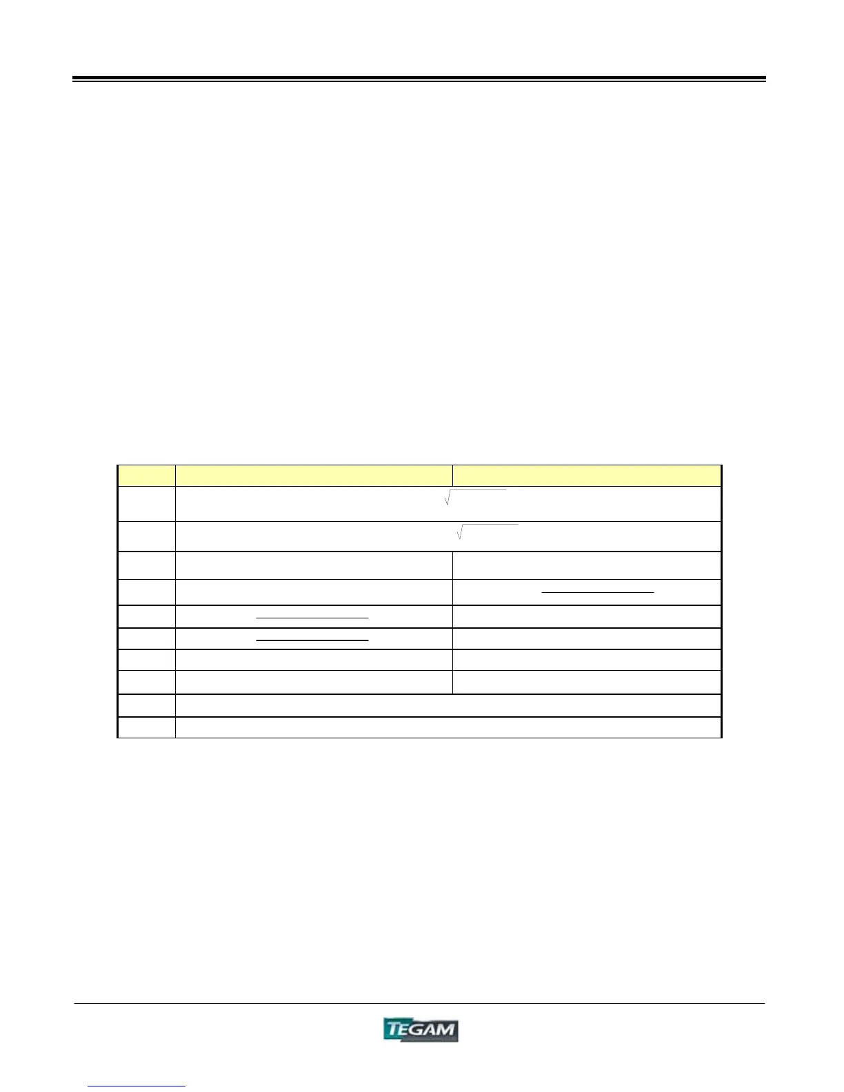
Table 1.9 – Series and Parallel Equivalent Circuit Measurements
Item Series Equivalent Circuits Parallel Equivalent Circuits
Z
|Z| = V/I( )
Y
|Y| = 1/|Z|( )
R
R
S
= ESR = | |Z|cosLJ | R
P
= EPR = | 1/(|Y|cosLJ) | = 1/G
X
X = |Z| sinLJ
G
|Y|cosLJ ***
B
B = |Y|sinLJ ***
L
L
S
= X/ǔ L
P
= 1/(ǔ*B)
C
C
S
= 1/(ǔ*X) C
P
= B/ǔ
D
D = 1/tanLJ = 1/Q
Q
Q = tanLJ = 1/D
R
2
+X
2
G
2
+B
2
*** ij is the Phase Angle of Admittance: ij = -LJ
L
S
, C
S
, R
S
represent the L, C, R measurements for series equivalent circuits.
L
P
, C
P
, R
P
represent the L, C, R measurements for parallel equivalent circuits.