5-13
3550 LCR Meter Instruction Manual Programming and Interfacing
RS-232C
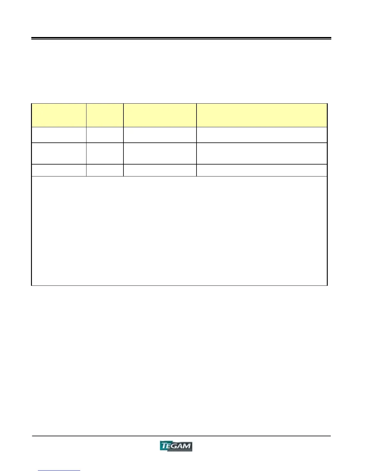
Table 5.3c – Command Summary cont’d
Function
Program
Code
Content
Remarks
Soft Version VER
Information on the Software
Version
Spot Correction Input
Number
SPX
Spot Correction Select from
1 to 3
“SP1”
Spot Correction
Frequency Limit
SPFXXX Set Spot Frequency “SPF42.0E0” ~ “SPF5.00E6”
*1) * indicates initial setting
*2) If a non-program code is entered, it will be considered invalid, and no setting will be made.
In this case, the previous setting will be unchanged.
NOTE 1: After receiving “L1”, only “L0”, “T0” and GET can be received.
NOTE 2: As soon as “MON” is sent, make sure that the system is ready to receive.
NOTE 3: Settings will vary according to the measurement range and measurement frequency.
Please refer to the range charts.
NOTE 4: After the termination of zero offset, the following indications are shown on the
computer.
“Correct OK” - Zero correction has executed properly
“Correct Error Impedance Under” – The open circuit impedance is less than 1kƻ, which is
beyond correction limits.
“Correct Error Impedance Over” The short circuit impedance has exceeded 1kƻ, which is
beyond correction limits.