4-23
Model 3550 LCR Meter Instruction Manual Operating Instructions
Making Accurate Measurements:
Connections to the Device Under Test (DUT)
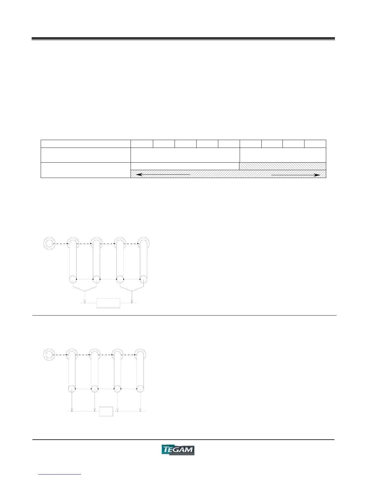
The relationship between the connections schemes and impedance, |Z| ranges are shown in Table
5-1. It is extremely important, for measurement accuracy purposes, to observe appropriate
connection methods for the subject test piece and measurement range.
Range 1 2 3 4 5 6 7 8 9
Impedance Mode
Low Impedance
(Series Equivalent Mode)
High Impedance
(Parallel Equivalent Mode)
3 Terminal Connection
Connection Type
5 Terminal Connection
3-Terminal Measurement
4 or 5-Terminal Measurements
GUARD
FORCE
SENSE
H
SENSE
H
FORCE
This measurement method is used for testing
devices having high impedance. In general,
components with large inductance, low
capacitance, or high resistance fall into this
category.
The major advantage to 3-terminal
measurements is that the influence of stray
capacitance and conductance between the test
leads and nearby conductors becomes negligible.
DU
GUARD
FORCE
SENSE
H
SENSE
H
FORCE
The 5-terminal measurement method can be
used for all impedance ranges and has significant
advantage over the 3-terminal measurement
method. The advantage is that in addition to
canceling the effects of stray capacitance and
conductance between the measurement leads
and close proximity conductors, the residual
inductance and resistance of the test lead are
bypassed by placing the voltage sense points of
contact directly at the DUT terminals.
A four-terminal measurement is the same as a
five-terminal measurement except that the guard
connection is not used.
GUARD
FORCE
SENSE
H
SENSE
H
FORCE
DU