C
LEAR
P
ATH
U
SER
M
ANUAL
R
EV
.
1.97
19
P
OWER
S
UPPLY
C
ONTROL
S
WITCH
The power supply for a ClearPath should not be switched on and off from
side, especially with
P
OWER
S
UPPLY
F
USING
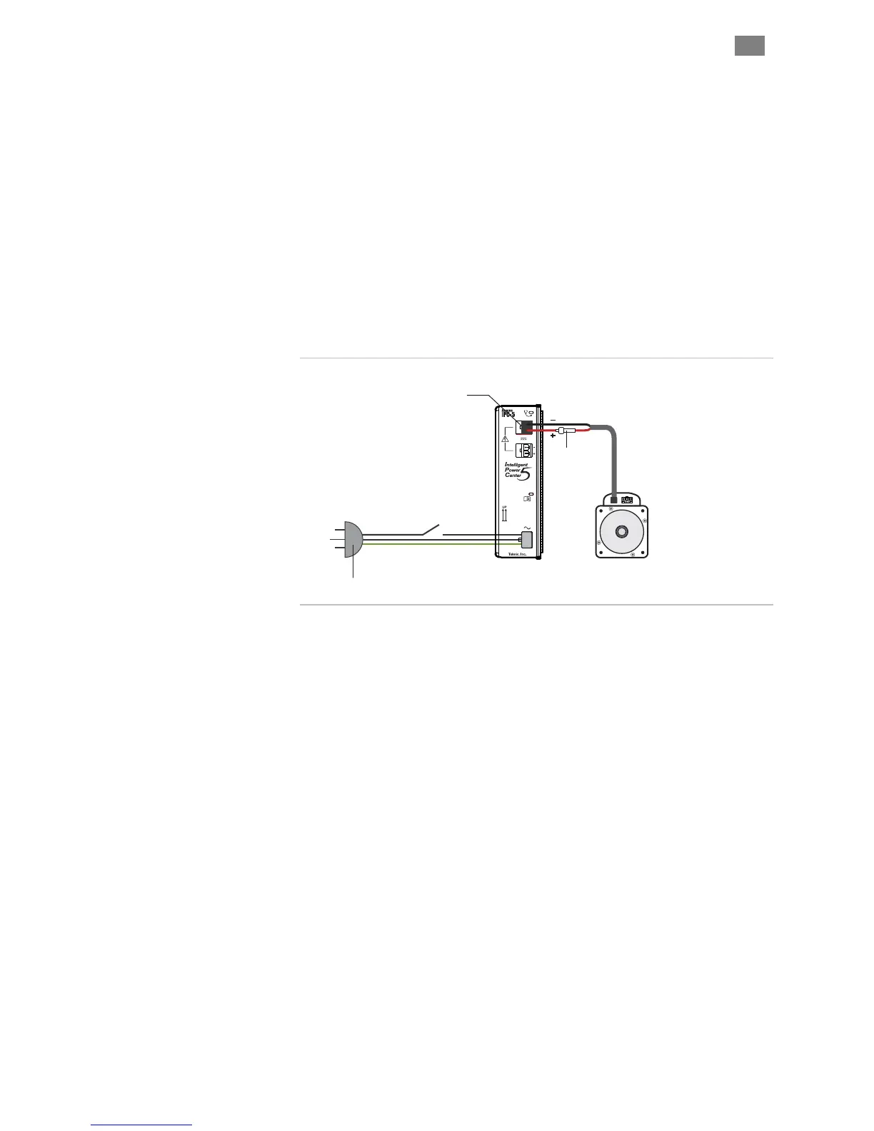
If you require an external fuse on your power supply’s DC output (to meet
compliance standards for example) it should be installed in line with the
positive leg of the DC output wiring as shown below. Use a maximum 10A
time delay fuse. Note: Teknic IPC power supplies are not internally fused
on the DC output side.
the DC output side. Switching the DC output
inexpensive relays, will ultimately result in poor performance (drop outs)
due to pitting, corrosion and contact welding. If a power switch is
required, install it such that the supply is disconnected from the AC input
side (see figure below).
Power Supply
(IPC-5 shown)
ClearPath Motor
If DC output fuse is required,
install in line with positive (+)
leg of DC output as shown.
If required, install power
switch on AC input side
of supply.
AC Input
DC Output
Fuse @10A Max.
Use slow blow type fuse
Fuse
Power supply switching and fusing detail
T
EKNIC
,
I
NC
.
F
AX
(585)784-7460
V
OICE
(585)784-7454