C
LEAR
P
ATH
U
SER
M
ANUAL
R
EV
.
1.97
44
M
ANUAL
V
ELOCITY
C
ONTROL
M
ODE
S
UMMARY
This mode offers fine velocity control from zero to a user defined
maximum at the turn of a quadrature output device (such as a quadrature
output encoder). Turn in one direction to increase CW motor velocity;
turn in the other direction to increase CCW velocity. When enabled,
ClearPath can either resume running at its last set speed or start at zero
speed (and stay at zero speed until commanded to move).
H
OW IT WORKS
Assert the Enable Input to energize the motor. Then, control motor
velocity by sending quadrature signals to ClearPath Inputs A and B. Each
quadrature signal transition (or “tick”) received by ClearPath causes an
incremental increase or decrease in motor velocity, depending on which
direction the encoder is turned (i.e. whether phase A leads B or B leads A).
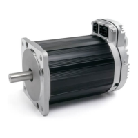
Signal Function Input Type
Input A
Motor velocity vs. time
Input B
Enable
Velocity Control A
Velocity Control B
Enable
NA NATrigger
Quadrature
Quadrature
Logic: High=Enable Low=Disable
0
1
0
1
0
1
t
v
Example Timing
Notes:
Manual Velocity Control
Velocity Control
Knob/encoder rotation reversed
Manual Velocity Control: Inputs and Timing Diagram
Notes:
• Disable time = 10 mS
Q
UADRATURE
S
IGNAL
S
OURCE
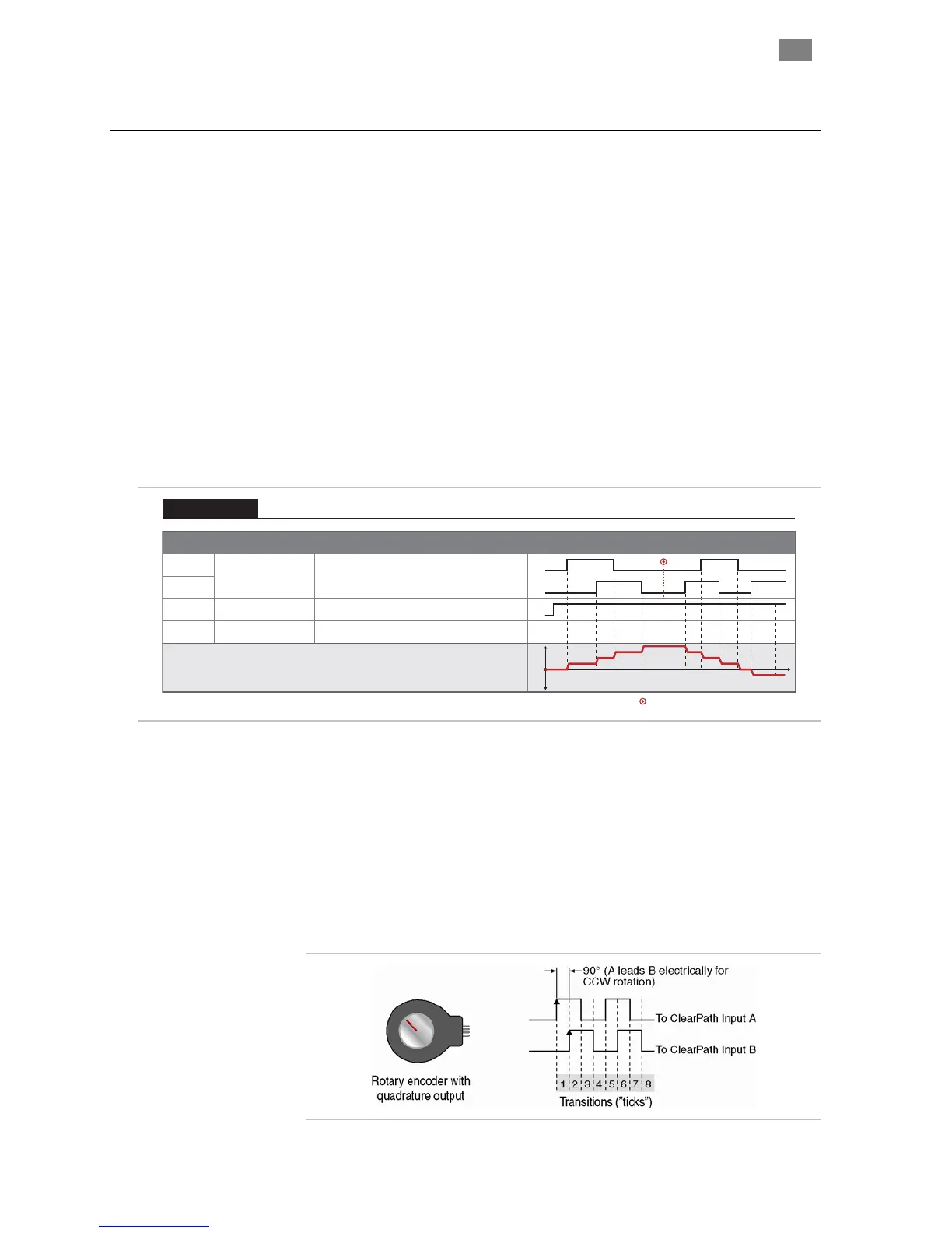
To use this mode you’ll need a device that can generate quadrature signals
in the 5-24VDC range. Many users choose an optical or mechanical
incremental encoder for this task, but a microcontroller or digital signal
generator will work as well. Note: mechanical quadrature encoders are
generally the least expensive option.
Quadrature output from a rotary encoder, aka “the knob”
T
EKNIC
,
I
NC
.
F
AX
(585)784-7460
V
OICE
(585)784-7454