C
LEAR
P
ATH
U
SER
M
ANUAL
R
EV
.
1.97
86
S
TEP AND
D
IRECT
ClearPath can be configured to move one count for each step received, or
steps] received (based on the Input Resolution setting).
ION
T
IMING
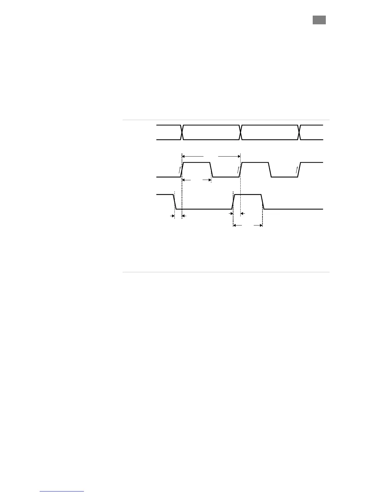
The ClearPath Step Input is “positive edge-triggered”, so ClearPath
registers a step only when Input B sees the rising edge of a step input
pulse (i.e. an electrical transition from low to high). Refer to the diagram
below for details and important step and direction signal timing
requirements.
one count per [x
Step
Position
Direction
n n-1 n+1n
t
cyc
t
pw
t
ds
t
ds
t
dh
t
ds
Minimum time between direction change and step input change = 25nS
t
cyc
Minimum step cycle time = 2uS
t
pw
Minimum step pulse width = 1 uS
t
dh
Minimum direction hold time = 1uS
Steps register on
rising edges only
Note: In this example, 1 step at Input B = 1 count of shaft motion. This ratio can be changed using Input Resolution setting.
Input B
Input A
ClearPath minimum step and direction input timing diagram
T
EKNIC
,
I
NC
.
F
AX
(585)784-7460
V
OICE
(585)784-7454