C
LEAR
P
ATH
U
SER
M
ANUAL
R
EV
.
1.97
47
R
AMP
U
P
/D
OWN
T
O
S
ELECTED
V
ELOCITY
M
ODE
S
UMMA
n any of four user defined
velocities.
H
OW IT WORK
e
immediately accelerates to the target velocity
RY
Changing the digital inputs on ClearPath (using your PLC, switches, etc.)
causes ClearPath to smoothly ramp betwee
S
Assert the Enable Input to get started. Once enabled, ClearPath reads th
state of Inputs A and B and
indicated. For example, if Input A is high and Input B is low
ClearPath will ramp to “Velocity 2”. Change to aq different velocity by
changing Inputs A and B.
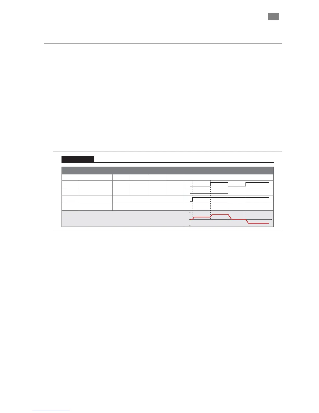
Signal Function Velocity Settings (logic levels) Example Timing
Input A
Motor velocity vs. time
Input B
Enable
Velocity Select A
Velocity Select B
Enable
NA NATrigger
Logic: High=Enable Low=Disable
0
1
0
1
0
1
0
1
t
v
0
Velocity 1 Velocity 2 Velocity 3 Velocity 4
LOW
LOW
HIGH
LOW
LOW
HIGH
HIGH
HIGH
Tip: Setting one of the programmable velocities to zero (Velocity 3 in the example
at right) provides a convenient way to stop the motor via the ClearPath inputs.
Velocity 1
Velocity 2
Velocity 3
Velocity 4
Ramp Up/Down to Selected Velocity (4 Velocity Programmable)
Velocity Control
Ramp Up/Down to Selected Velocity Mode: Inputs and Timing Diagram
Notes:
• As soon as a new velocity command is received by ClearPath—as
happens when Inputs A and/or B are changed—ClearPath
immediately ramps to the new target velocity without delay.
• For a convenient way to command ClearPath to stop, set one of
the velocity settings to zero. We did this with “Velocity 3” in the
table above.
• Disable time = 10 mS
T
EKNIC
,
I
NC
.
F
AX
(585)784-7460
V
OICE
(585)784-7454