C
LEAR
P
ATH
U
SER
M
ANUAL
R
EV
.
1.97
62
F
OLLOW
D
IGITAL
T
ORQUE
C
OMMAND
(U
NIPOLAR
PWM
I
NPUT
)
M
ODE SUMMA
Connect a digital PWM waveform from your PLC or other device, and
ClearPath will run at a speed proportional to the duty cycle of the PWM
waveform.
H
OW IT WORKS
Assert the Enable Input to energize the motor. Motor torque is controlled
be applying a variable PWM signal to Input B. 0% PWM duty cycle
commands zero torque, and 100% duty cycle commands full-scale torque.
Changes in speed occur at the user-defined acceleration rate. Direction of
shaft rotation is controlled by the state of Input A. See Inputs and Timing
table below.
RY
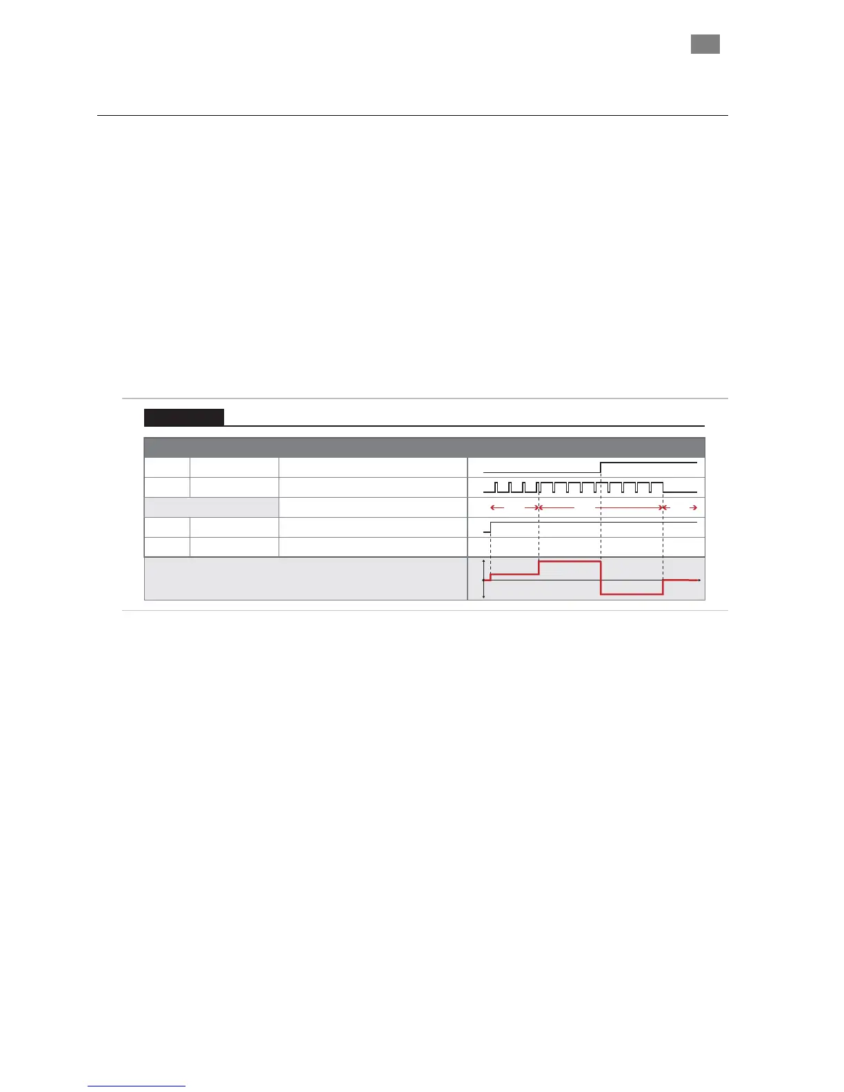
Signal Function Input Type
Input A
Motor torque vs. time
Input B
Enable
Direction
Torque
Enable
NA NATrigger
Logic: High=CW Low=CCW
Pulse: Variable PWM
Logic: High=Enable Low=Disable
0
1
0
1
t
tq
Example Timing
Notes:
0
1
0
1
Duty cycle of applied PWM signal (%)
90%10% OFF
Variable Torque With Unipolar PWM Input Control
Torque Control
Variable Torque Mode
50mS (or more) the PWM input is
ue
• Disable time = 10 mS
(Unipolar PWM Control): Inputs and Timing Diagram
Notes:
• PWM input frequency range: 20 Hz to 30 kHz.
• If the PWM signal is off for
considered off. This is interpreted by ClearPath as a zero-torq
command.
T
EKNIC
,
I
NC
.
F
AX
(585)784-7460
V
OICE
(585)784-7454