Do you have a question about the Teknik ClearPath and is the answer not in the manual?
Important warning about the power and dangers of ClearPath motors.
Describes how to run the motor using software controls in Manual Velocity Mode.
Guidelines for personal safety when operating ClearPath motors.
Warnings related to CE compliance for ClearPath systems.
Legal disclaimer regarding product suitability and user responsibility.
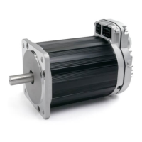
Explains the components and concept of an all-in-one ClearPath servo system.
Identifies and describes the key components of a ClearPath motor.
Provides a summary of the Absolute Positioning mode's operation.
Illustrates how to command a move in the Absolute Positioning mode.
Details on ClearPath inputs (Enable, A, B) and outputs (HLFB).
Guidance on selecting the appropriate power supply for ClearPath motors.
Details on ClearPath power supply voltage and current requirements.
Advice on ideal power supplies and why to avoid certain types.
Crucial safety checks before connecting DC power to the ClearPath.
Information on power supply switching and fusing requirements.
Details on ClearPath's digital inputs (Enable, Input A, Input B).
Specifies the minimum current required for ClearPath input signals.
Explains the function and operation of the Enable input.
Describes how Inputs A and B function as control inputs.
Details the different High-Level Feedback output modes.
Tips for connecting microcontrollers to ClearPath inputs.
Covers MSP system requirements and installation procedures.
Steps to establish communication between PC and ClearPath.
Detailed steps for first-time communication setup.
Important notes and considerations for using MSP software.
Overview of the main user interface elements of ClearPath MSP.
Explanation of the Mode Controls section in MSP.
Lists the key features and capabilities of the MSP Scope tool.
Reference guide for interpreting the Strip Chart display.
Describes the functions available in the File, Edit, Mode, and Setup menus.
Setting to limit maximum torque when Move Done criteria are met.
Setting a limit for tracking error to prevent shutdowns.
Configuration options for High-Level Feedback (HLFB).
Explains the criteria for achieving Move Done status.
Overview table of available operational modes for the MC Family.
Details on ClearPath velocity control operational modes.
Details on ClearPath torque control operational modes.
Details on ClearPath position control operational modes.
Explanation of the Pulse Burst Positioning operational mode.
Summary of the Spin On Power Up operational mode.
Explanation of the operation of the Spin On Power Up mode.
Summary of the Manual Velocity Control operational mode.
Explanation of the operation of the Manual Velocity Control mode.
Details on settings related to encoder and knob configuration.
Defines the motor velocity increment per quadrature tick.
Allows reversing the motor's direction sense relative to quadrature phasing.
Checkbox to configure how ClearPath handles quadrature transitions.
Summary of the Ramp Up/Down to Selected Velocity mode.
Explanation of the operation of the Ramp Up/Down mode.
Summary of the Bi-Polar PWM Velocity Control mode.
Explanation of the Bi-Polar PWM Velocity Control mode operation.
Explains the benefits and use of a PWM deadband setting.
Summary of the Unipolar PWM Velocity Control mode.
Explanation of the Unipolar PWM Velocity Control mode operation.
Illustrates the relationship between motor velocity and PWM duty cycle.
Summary of the Frequency Input Velocity Control mode.
Explanation of the Frequency Input Velocity Control mode operation.
Summary of the Bi-Polar PWM Torque Control mode.
Explanation of the Bi-Polar PWM Torque Control mode operation.
Explains the benefits of using a PWM deadband for torque control.
Summary of the Unipolar PWM Torque Control mode.
Explanation of the Unipolar PWM Torque Control mode operation.
Illustrates the relationship between motor torque and PWM duty cycle.
Summary of the Frequency Input Torque Control mode.
Explanation of the Frequency Input Torque Control mode operation.
Summary of the 2-Position Absolute Move mode.
Explanation of the 2-Position Absolute Move mode operation.
Defines absolute position referenced from a home position.
Procedure for setting up switch-based homing.
Summary of the 4-Position Absolute Move mode.
Defines absolute position referenced from a home position.
Explanation of the 4-Position Absolute Move mode operation.
Procedure for configuring automatic hard stop homing.
Details the 2-Distance Incremental Move mode.
Details the 4-Distance Incremental Move mode.
Summary of the ClearPath SD (Step and Direction) mode.
Explanation of the ClearPath SD mode operation.
Dimensional drawings for ClearPath NEMA 34 motors.
Dimensional drawings for ClearPath NEMA 23 motors.
General considerations for mounting ClearPath motors.
Guidance on connecting ClearPath to mechanical systems.
General tips and guidelines for connecting motor shafts.
Notes and recommendations for selecting couplings.
Instructions for installing pulleys and pinions onto the motor shaft.
Information on different types of end-of-travel stops.
Guidance on mounting fans for cooling ClearPath motors.
Pinout information for ClearPath I/O cables.
Pinout information for ClearPath power cables.
Specifications for electrical power requirements and I/O.
Specifications for motor bearings and environmental conditions.
Information on regulatory compliance and product warranty.
Guidelines for Protective Earth (PE) connection and grounding.
Recommendations for proper power return wiring.
Explains the structure and meaning of ClearPath part numbers.
Defines terms and explains encoder/positioning resolution types.
How to set input resolution within MSP software.
Examples of why and how to adjust input resolution settings.