C
LEAR
P
ATH
U
SER
M
ANUAL
R
EV
.
1.97
18
C
ONNECTING
P
OWER TO A
C
LEAR
P
ATH
M
OTOR
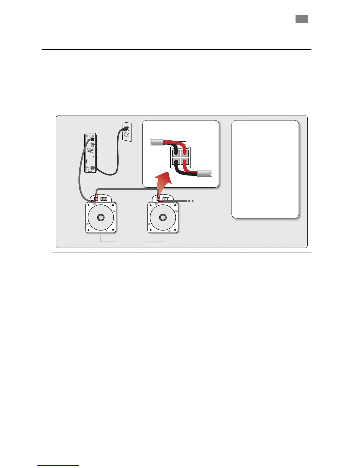
Connect main DC power to the ClearPath power connector, a four positio
Molex Minifit Jr. connector. For applications with multiple ClearPath
motors, power can be daisy-chained from motor to motor as shown below.
n
The diagram below includes a list of power connector mating parts readily
available from most electronic component suppliers.
Power Supply
(IPC-5 shown)
ClearPath Motors
2. GND 1. V+
4. GND 3. V+
Power Connector Pinout
Connector Housing 4 pos.
Molex/39-01-9042 (black)
Terminals 16AWG
Molex/39-00-0078 (loose)
Molex/39-00-0077 (reel)
Crimp Tool 16-24 AWG
Molex/63819-0900
Terminal Extractor Tool
Molex/11-03-0044
Mating Parts
Cable Stock 2/16AWG (black)
Belden/90410
ClearPath Power Supp
B
EFORE
P
OWE
wer
cause electrical arcing that can damage the connector pins
over time.
• Never connect a ClearPath motor directly to an AC outlet.
This will damage the ClearPath motor and void the warranty.
• It is acceptable to daisy chain power to several ClearPath
motors provided that the combined current draw of the
motors does not exceed 10A during operation. If total
combined current draw is expected to exceed 10A, star power
wiring should be used.
• When a ClearPath motor is powered on, a startup routine
energizes the motor for a few milliseconds. During this
startup routine it is not uncommon for a small amount of
motion to occur (1˚ typical).
ly Connection
RING A
C
LEAR
P
ATH
• Check for proper DC power polarity before connecting po
to a ClearPath. Reversing DC power polarity may damage the
unit and void the warranty.
• Verify that the power supply is turned off and discharged
before connecting to a ClearPath. Connecting and
disconnecting the motor from a charged power supply will
T
EKNIC
,
I
NC
.
F
AX
(585)784-7460
V
OICE
(585)784-7454