C
LEAR
P
ATH
U
SER
M
ANUAL
R
EV
.
1.97
52
S
ETTING
PWM
etting” by ClearPath. This gives the user
M
gh” to) 50%.
A
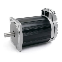
The deadband expands the range about the 50% PWM mark that is
n erpreted as the “zero-velocity s
D
EADBAND
(O
PTIONAL
)
i t
a reliable way to ensure that motor velocity ramps to zero when the PW
duty cycle is set at (or “close enou
Max. Velocity
(CCW Rotation)
Velocity = 0
Deadband
(+/- 5%)
10 20 30 40 50 60 70 80 90 1000
Max. Velocity
(CW Rotation)
Duty Cycle
+/- 5% PWM dead band setting
Why use a deadband?
In bi-polar mode, stopping the motor (i.e. commanding “zero velocity”) is
achieved, in theory, by applying a 50% duty cycle PWM signal to Input B.
However, it can be technically challenging to set a perfect 50% duty cycle.
In fact, some very low speed motion may still be observed at the motor
shaft even when duty cycle is apparently set to 50%. A deadband helps to
ensure that actual motor velocity is zero (with no drift) when you expect it
to be.
Example: If the user sets a +/- 5% dead band, any PWM signal with a
duty cycle between 45% and 55% will be interpreted as a zero-velocity
command by ClearPath. See figure above.
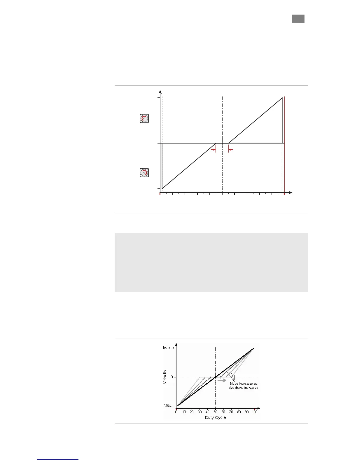
Note: As size of deadband setting increases, the slope of velocity vs. duty
cycle increases as illustrated below.
T
EKNIC
,
I
NC
.
F
AX
(585)784-7460
V
OICE
(585)784-7454