C
LEAR
P
ATH
U
SER
M
ANUAL
R
EV
.
1.97
56
F
OLLOW
D
IGITAL
V
ELOCITY
C
OMMAND
(F
REQUENCY
I
NPUT
)
M
ODE SUMMARY
Connect a digital variable frequency waveform from your PLC or other
device, and ClearPath will run at a velocity proportional to the frequency
of the waveform.
H
OW IT
W
ORKS
Assert the Enable Input to energize the motor. Then, control velocity by
applying a variable frequency pulse train to Input B. Pulse frequency is
proportional to commanded velocity. Direction of travel (CW/CCW) is
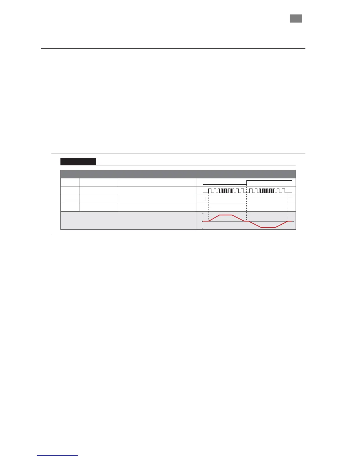
controlled by the state of Input A. See Inputs and Timing table below.
Signal Function Input Type
Input A
Motor velocity vs. time
Input B
Enable
Direction
Velocity
Enable
NA NATrigger
Logic: High=CW Low=CCW
Pulse: Variable Frequency
Logic: High=Enable Low=Disable
0
1
0
1
t
v
Example Timing
Notes:
0
1
0
1
Follow Digital Velocity Command (Frequency Input Control)
Velocity Control
Follow Digital Velocity Command (Frequency Input Control): Inputs and Timing Diagram
Notes:
• Input frequency range: 20 Hz to 500 kHz.
• If the frequency signal is off for 50mS or more the input is
considered off. This is interpreted by ClearPath as a zero-
velocity command.
• Disable time = 10 mS
T
EKNIC
,
I
NC
.
F
AX
(585)784-7460
V
OICE
(585)784-7454