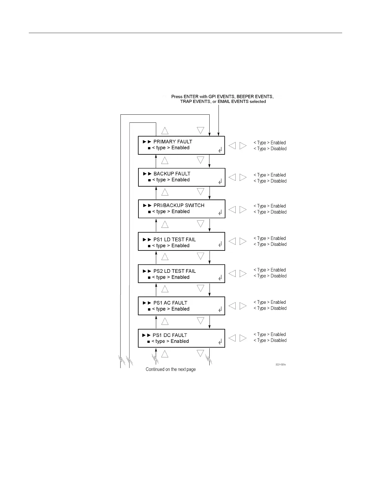
Home
Tektronix
Control Unit
ECO8000 Series
Tektronix ECO8000 Series User Manual
4
of 1
of 1 rating
124 pages
Give review
Manual
Specs
To Next Page
To Next Page
To Previous Page
To Previous Page
Loading...
Menus
Press
the
up
(
▲
)
or
down
(
▼
)
arrow
button
to
select
an
event
type,
and
then
press
the
left
(
◄
)
or
right
(
►
)
arrow
button
to
enable
or
disable
noti
fi
cation
for
that
event
type.
Press
the
ENTER
button
to
implement
the
selection.
Fig
ure
28:
<type>
EVENTS
submenu
–
part
1
84
ECO8000
Series
Automatic
Changeover
Unit
User
Manual
105
107
Table of Contents
Table of Contents
7
Important Safety Information
10
General Safety Summary
10
Service Safety Summary
12
Terms in this Manual
13
Symbols and Terms on the Product
13
Compliance Information
14
EMC Compliance
14
Safety Compliance
15
Environmental Considerations
17
Preface
19
Product Description
19
Product Documentation
21
Conventions Used in this Manual
21
Getting Started
23
Initial Product Inspection
23
Accessories
24
Table 1: Standard and Optional Accessories
24
Product Installation
25
Table 2: ECO8000 Series Environmental Requirements
25
Figure 1: Installing or Removing the Instrument into or from the Rack
27
Table 3: AC Line Power Requirements
28
Network Installation
29
Figure 2: Location of Rear Panel Power Connectors (ECO8000 Shown)
29
System Considerations
33
Signal Connections
34
Table 4: Example Plan for Connecting Signals to an ECO8000
34
Figure 3: ECO8000 and SPG8000 System Installation Example
35
Table 5: ECO8000 and SPG8000 System Installation Example Connections
35
Figure 4: ECO8020 and SPG8000 System Installation Example
37
Table 6: ECO8020 and SPG8000 System Installation Example Connections
37
Operating Basics
39
Operational Overview
39
Figure 5: ECO8000 Series Subsystems (ECO8020 with Option DPW Shown)
39
Controls, Connectors, and LED Indicators
41
Figure 6: ECO8000 Controls and Connectors
41
Figure 7: ECO8020 Controls and Connectors
41
Table 7: GPIO Connector Signal Pinouts
44
Table 8: LTC/SPG Connector Signal Pinouts
45
Table 9: LTC out Connector Signal Pinouts
46
Table 10: Power on LED States for a Power Supply Module
47
Table 11: Power off LED States for a Power Supply Module
48
Table 12: Self Test Error Codes
49
Initial Product Setup
50
Table 13: SPG Trigger Cable Connections and GPI Configuration
54
Table 15: Signal Pinouts for the SPG8000 GPI Connector
55
Table 16: Signal Pinouts for the TG8000 GPI Port
55
How to Operate an Instrument with Two Power Supplies (Option DPW Only)
58
Figure 8: Removing a Power Supply Module
61
How to Upgrade the Instrument Firmware
62
Figure 9: Installing the Backup or Replacement Power Supply Module
62
Figure 10: Sample of Transfer.exe Window after the Upgrade Is Complete
67
How to Use the Event Log and Event History
70
Table 17: Fault and Event Descriptions
71
Table 18: Relationship between Module and Channel Numbers
72
Table 19: Board Voltage Error Codes
73
Menus
75
Menu Navigation
75
Main Menu
76
Figure 11: Main Menu
76
STATUS Menu
78
Figure 12: STATUS Menu
78
Figure 13: EVENT LOG (by TYPE) Submenu - Part 1
80
Figure 14: EVENT LOG (by TYPE) Submenu - Part 2
81
Figure 15: EVENT LOG (by TYPE) Submenu - Part 3
82
Figure 16: EVENT LOG (by TIME) Submenu
83
CHANNEL Menu
84
Figure 17: CHANNEL Submenu
84
Figure 18: Custom Level Threshold Display
85
SYSTEM CONFIG Menu
87
Figure 19: SYSTEM CONFIG Menu - Part 1
87
Figure 20: SYSTEM CONFIG Menu - Part 2
88
Figure 21: SYSTEM CONFIG Menu - Part 3
89
Figure 22: NETWORK CONFIG Submenu
94
Figure 23: SNMP CONFIG Submenu
96
Figure 24: EMAIL REPORTING Submenu
98
Figure 25: INTERNAL CLOCK Submenu
101
Figure 26: SET LOCAL TIME Submenu
102
Figure 27: DST SCHEDULE Submenu
103
Table 20: Event Reporting Methods and Menu Access Points
105
Figure 28: <Type> EVENTS Submenu - Part 1
106
Figure 29: <Type> EVENTS Submenu - Part 2
107
Figure 30: <Type> EVENTS Submenu - Part 3
108
Figure 31: OPTIONS ENABLED Submenu
109
Figure 32: DIAGNOSTICS Submenu - Part 1
111
Figure 33: DIAGNOSTICS Submenu - Part 2
112
Table 21: Relationship between Module and Channel Numbers
114
Remote Control
117
How to Use the Web Interface
117
Figure 34: Example ECO8020 Web Interface Window
119
How to Use SNMP
120
Table 22: Elements of the Web User Interface
120
Table 23: SNMP Parameters
121
Other manuals for Tektronix ECO8000 Series
Service Manual
106 pages
4
Based on 1 rating
Ask a question
Give review
Questions and Answers:
Need help?
Do you have a question about the Tektronix ECO8000 Series and is the answer not in the manual?
Ask a question
Tektronix ECO8000 Series Specifications
General
Brand
Tektronix
Model
ECO8000 Series
Category
Control Unit
Language
English
Related product manuals
Tektronix TM 504
49 pages
Tektronix TM 502A
58 pages
Tektronix TM 503
46 pages