Operating Basics
Operational o
verview
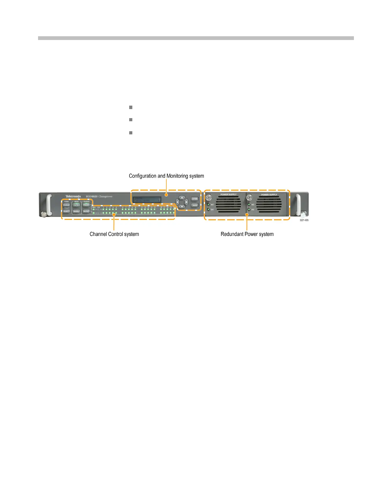
The ECO8000 Series has three main subsystems:
Channel Control system
Configuration and Monitoring system
Redundant Power system
These thre
e subsystems are loosely coupled to assume maximum reliability of the
main ECO function, which is sensing faults on the input signals and switching to
a backup if necessary.
Figure 5: ECO8000 Series subsystems (ECO8020 with Option DPW shown)
Channel Control system
The Channel Control system monitors the level on each input, and switches to the
other sync source if a fault occurs. This subsystem is implemented as a simple
hardware state m achine to maximize reliability. This portion of the instrument is
accessed via the left keyboard, and the status is displayed on the button lights and
the per-channel LEDs on the front panel.
If the instrument is in A UTO mode, then the Channel Control system locks out
any changes from the other subsystems. This prevents most issues in the other
su
bsystems from impacting the basic operation of the ECO.
When the instrument powers on, the Channel Control system restores all basic
c
onfiguration settings that were in place wh en the instrument was powered off.
This restoration i s independent of the processor booting to run the display and
the Configuration and Monitoring system. If the Configuration and Monitoring
system is rebooted, the Channel Control system is unaffected.
If the instrument loses power, the REF/ELSW channels will automatically switch
from electronic to relay mode to maintain the s ignal throughput. These channels
will automatically switch back to electronic mode when power is restored. When
the REF/ELSW channels switch from electronic mode to relay mode and back,
the sync on these channels will experience a momentary glitch.
ECO8000 Series Automatic Changeover Unit User Manual 17

 Loading...
