Operating Basics
Diagnostic board voltage
error codes
Diagnostic vol
tages are read by the instrument every second and any out of
tolerance results are sent to the Fault Manager. If any voltage failure occurs, it
will be reported in the following ways:
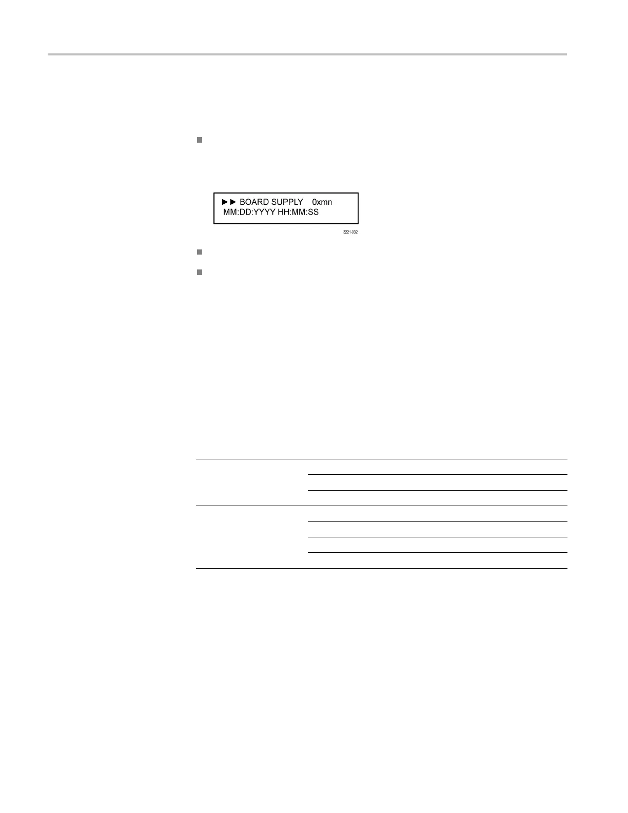
An error message is written o n the front panel LCD in the STATUS: FAULTS
display with the code “0xmn” listed in the boxrepresentingtheerrorcodeas
shown below. The letter “m” represents the board number and “n” represents
the index on that board. In the case of board 0, the leading 0 is truncated.
A similar message, which includes the event code, is entere d in the Event Log.
If the u ser-configurable event reporting methods (SNMP trap, e-mail, GPI
signal, instrument beeper) are enabled to notify in the event of a voltage error,
then a message is sent using the e nabled method(s).
Event codes. The e vent code consists of two numbers, where the first number
repres
ents the board and the second number represents the voltage index of the
board. The Main board number is 0 and the m odule board numbers are 1 to 4.
Depen
ding on the configuration of your instrument, only some of the modules
may b e installed. The relationship between the module number and the channel
numbers of an instrument are a s follows:
Table 18: Relationship between module and channel numbers
Instrument model Module number Chan nel num bers
1 1–3
2 4–6
ECO8000
3 7–9
1 1–5
2 6–10
3 11–15
ECO8020
4 16–20
The modules can be either REF/ELSW or HREF/Relay boards. The REF boards
do not have the + 3.1RL voltage. The index number is the same for all module
types. The following table lists the possible code combinations.
50 ECO8000 Series Automatic Changeover Unit User Manual

 Loading...
