Removal and Installation Procedures
3.
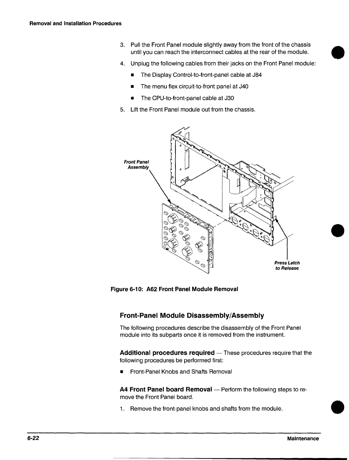
Pull the Front Panel module slightly away from the front of the chassis •
until you can reach the interconnect cables at the rear of the module.
4. Unplug the following cables from their jacks on the Front Panel module:
•
The Display Control-to-front-panel cable at J84
• The menu flex circuit-to-front panel at J40
•
The CPU-to-front-panel cable at J30
5. Lift the Front Panel module out from the chassis.
Front Panel
Assembly
Figure
6-10: A62
Front
Panel
Module
Removal
Front-Panel
Module
Disassembly/Assembly
Press Latch
to Release
The following procedures describe the disassembly of the Front Panel
module into its subparts once it
is
removed from the instrument.
Additional
procedures
required
- These procedures require that the
following procedures be performed first:
• Front-Panel Knobs and Shafts Removal
A4
Front
Panel
board
Removal-
Perform the following steps to re-
move the Front Panel board.
•
1. Remove the front-panel knobs and shafts from the module. •
6-22 Maintenance
 Loading...

