•
•
•
/'
/'
r
/'
/'
/'
1
1
1
1
1
1
Removal and Installation Procedures
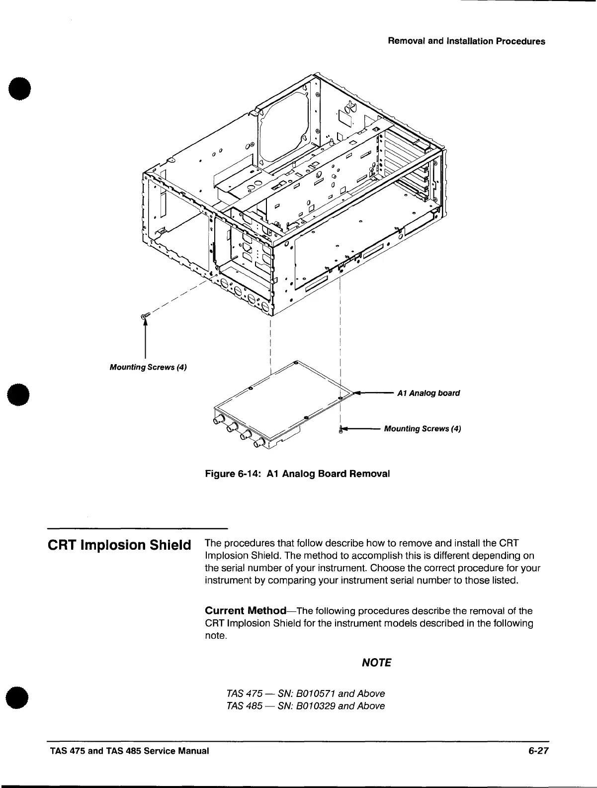
Mounting Screws (4)
1/,11
CRT Implosion Shield
/
~'-----
~
A1
Analog board
i-
Mounting
Screws
(4)
Figure 6-14:
A1
Analog Board Removal
The procedures that follow describe how
to
remove and install the CRT
Implosion Shield. The method to accomplish this
is
different depending on
the
serial number of your instrument. Choose the correct procedure for your
instrument by comparing your instrument serial number to those listed.
Current
Method-The
following
procedures
describe
the
removal
of
the
CRT
Implosion Shield for the instrument models described
in
the following
note.
NOTE
TAS
475
- SN: 8010571
and
Above
TAS
485
- SN: 8010329
and
Above
TAS 475 and TAS 485 Service Manual
6-27
 Loading...

