Performance Tests
4-26
8.
Press the TRIGGER MENU button and make the following selections
.-
from the main trigger menu:
• Set MODE
to
Auto
• Set SRC to Ch1
• Set CPLG to DC
• Set SLOPE to Rising
9.
Press the MAIN/DELAY SELECT button and make the following selec-
tions from the delay trigger menu:
• Set MODE
to
Runs After
• Set SRC to
Ch1
• Set CPLG to DC
• Set SLOPE to Rising
10.
Set the delayed sec/div scale to 50 ns.
11. Press the
HORIZONTAL MENU button and select
DELAY.
12. Set the delay time to 15 ns using the General Purpose Knob.
13.
Set DELAY to Off.
14.
Adjust the sine wave generator amplitude for a three division display.
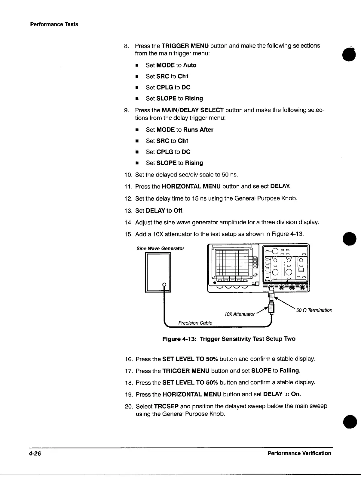
15.
Add a 10X attenuator to the test setup
as
shown
in
Figure 4-13.
Sin
e
Wave
Generator
I I
=--0
00
I
00
a
a
~.
'0'
10
a
. 0
0
. a
10
[a
0
10
E3
@
·0
~o
0
00
a 0 a a a
-::r
)
•
'-'
'-'
'-'
'-'
~,
;.ii\=~=~=~,
/~50Qr.
tOX
Attenuator )
ermination
Precision Cable
Figure 4-13: Trigger Sensitivity Test Setup Two
16. Press the
SET LEVEL TO 50% button and confirm a stable display.
17. Press the
TRIGGER MENU button and set SLOPE to Falling.
18. Press the
SET LEVEL TO 50% button and confirm a stable display.
19. Press the
HORIZONTAL MENU button and set DELAY to On.
20.
Select TRCSEP and position the delayed sweep below the main sweep
using the General Purpose Knob.
Performance Verification
•
•
 Loading...

