Brief Performance Checks
4-4
Functional Tests Prerequisites
1.
Power on the oscilloscope and allow a
20
minute warm-up before per-
forming this procedure; adjust the READOUT
control to display the
readout and the
INTENSITY control to display waveforms.
2.
Disable the dual delay with the following menu selections.
a.
Press the UTILITY button and select CONFIG from the main menu.
b.
Select MORE until you can select Dual Delay Disabled.
3.
Press the ALT/CHOP, ADD button and set ADD1
+2
and
ADD3+4
to
Off.
4.
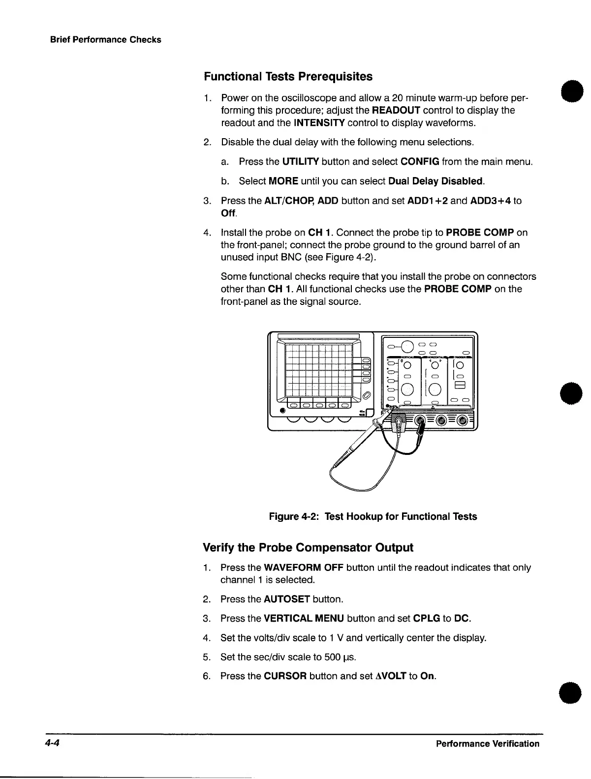
Install the probe
on
CH
1.
Connect the probe tip to PROBE COMP on
the front-panel; connect the probe ground to the ground
barrel of
an
unused input BNC (see Figure 4-2).
Some functional checks require that you install the probe on connectors
other than
CH
1.
All functional checks use the PROBE COMP on the
front-panel
as
the signal source.
Figure 4-2: Test
Hookup
for
Functional Tests
Verify the Probe Compensator Output
1.
Press the WAVEFORM OFF button until the readout indicates that only
channell
is
selected.
2.
Press the AUTOSET button.
3.
Press the VERTICAL MENU button and set CPLG to DC.
4.
Set the volts/div scale to 1 V and vertically center the display.
5.
Set the sec/div scale to 500
I1s.
6.
Press the CURSOR button and set AVOLT to On.
Performance Verification
•
•
•
 Loading...

