•
•
•
Removal and Installation Procedures
2.
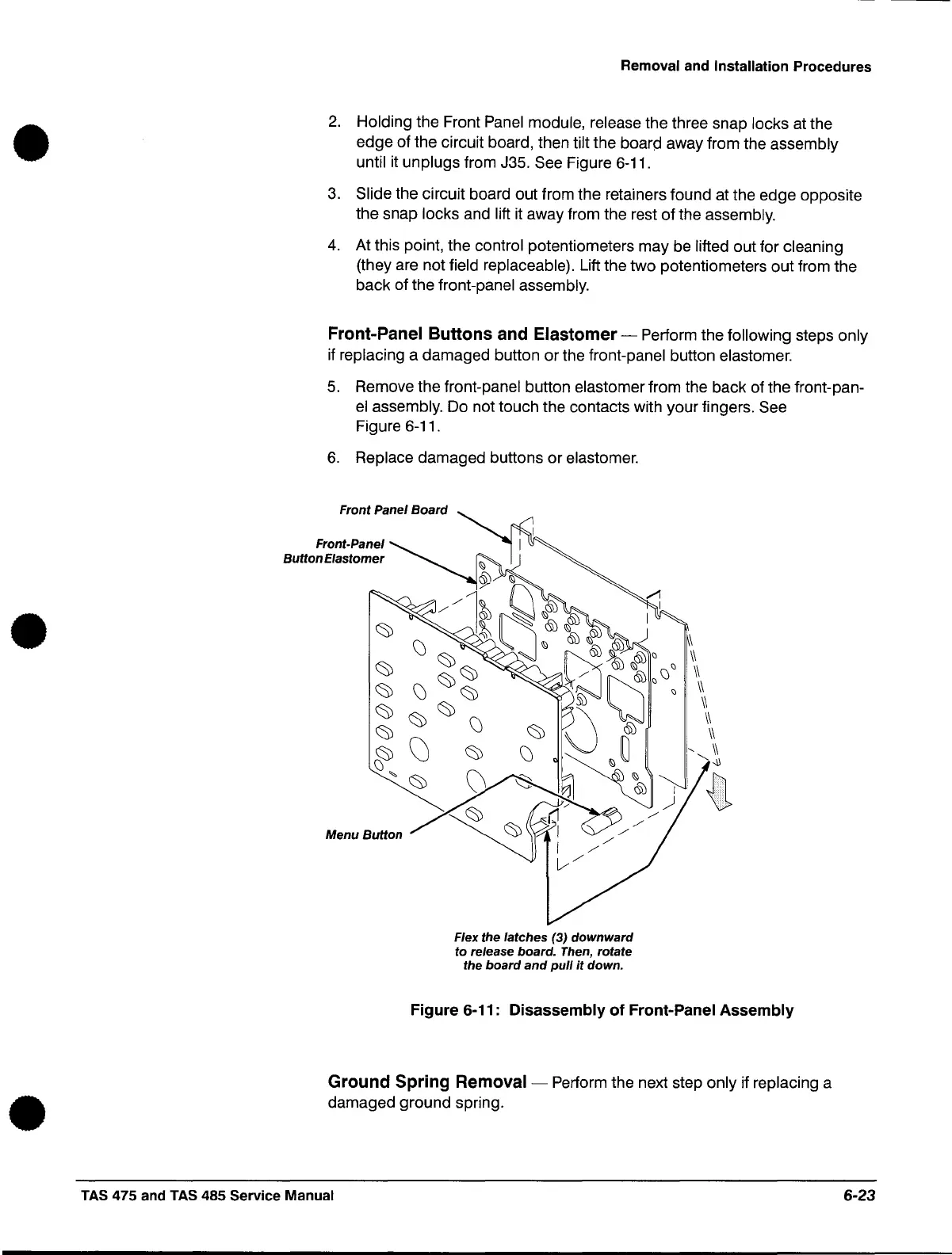
Holding the Front Panel module, release the three snap locks at the
edge
of
the circuit board, then tilt the board away from the assembly
until
it
unplugs
from J35. See Figure 6-11.
3.
Slide the circuit board out from the retainers found at the
edge
opposite
the
snap locks and lift it away from the rest
of
the assembly.
4.
At this point, the control potentiometers
may
be lifted
out
for cleaning
(they are not field replaceable). Lift the
two
potentiometers
out
from the
back
of
the front-panel assembly.
Front-Panel Buttons and Elastomer - Perform the following steps
only
if replacing a
damaged
button
or
the front-panel button elastomer.
5.
Remove the front-panel button elastomer from the back
of
the front-pan-
el
assembly. Do not touch the contacts with
your
fingers. See
Figure 6-11.
6.
Replace
damaged
buttons
or
elastomer.
Front Panel
Board
Front-Panel
Button
Elastomer
Menu
Button
Flex the
latches
(3)
downward
to release board. Then, rotate
the
board
and
pull
it
down.
\
II
II
II
II
II
II
"
II
,,~
{1
Figure
6-11:
Disassembly
of
Front-Panel
Assembly
Ground Spring Removal - Perform the next step
only
if replacing a
damaged
ground
spring .
TAS
475 and TAS 485 Service Manual 6-23
 Loading...

