•
•
•
Adjustment Procedures
6.
Set the
DC
calibration generator for 1
VDC
output.
7.
Select Done when completed.
8.
Set the DC calibration generator for 100 mVDC output.
9.
Select Done when completed.
10.
Disconnect the test setup.
11.
Select Done when completed.
This portion of the routine takes
less than two minutes to complete.
NOTE
The
following steps use both the General Purpose Knob
and
the
TOGGLE button
to
make adjustments.
The
General Purpose Knob
performs two functions: adjust horizontal gain
and
centering.
The
TOGGLE button selects the function
of
the General Purpose Knob.
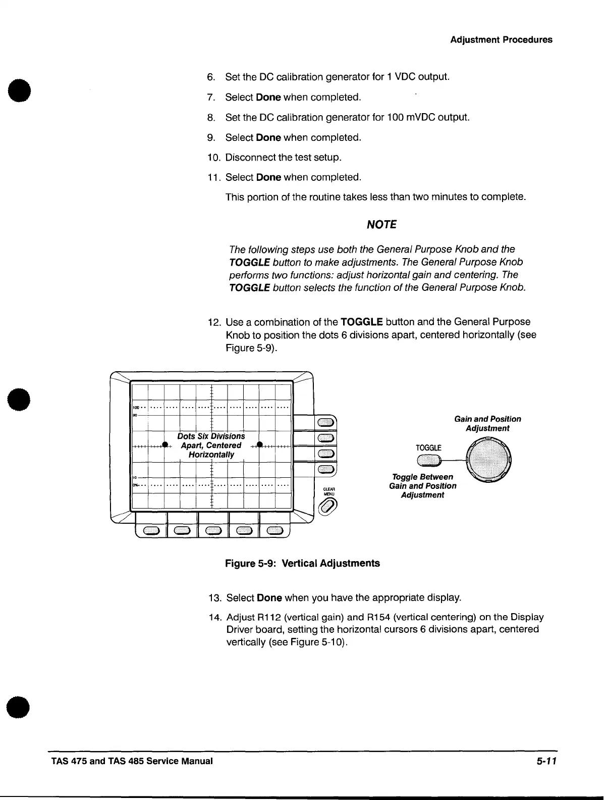
12.
Use a combination of the TOGGLE button and the General Purpose
Knob to position the dots 6 divisions apart, centered horizontally (see
Figure 5-9).
100
••
•••• •••• ••••
••••
••••
•••• ••••
••••
•
•••
oo~--+-~-+~~~-+~~+-~~--~~
Dots' Six Divisions
Apart,
Centered
Horizontally
0'lI0
••
'
••••••••••••••••••••••••••••••••••••
ClEAR
MENU
~~J~~~~~~~~~I~f:-....--
@
Lo
0 0 0
OJ
Figure 5-9: Vertical Adjustments
Gain
and
Position
Adjustment
Toggle Between
Gain and Position
Adjustment
13.
Select Done when you have the appropriate display.
14.
Adjust
R112
(vertical gain) and
R154
(vertical centering) on the Display
Driver board, setting the horizontal cursors 6 divisions apart, centered
vertically (see Figure 5-10).
TAS
475 and TAS 485 Service Manual
5-11
 Loading...

