Troubleshooting
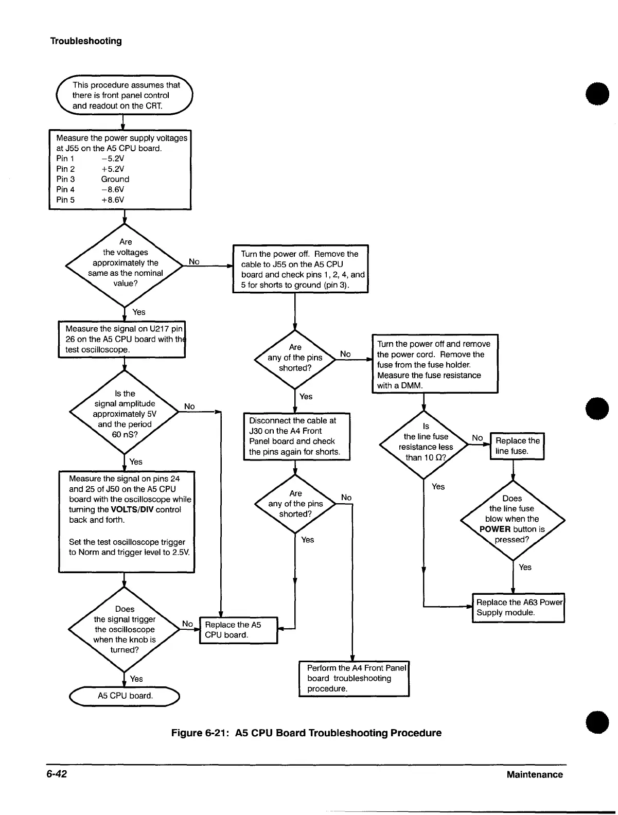
This procedure assumes that
there
is
front panel control
and readout on the
CRT.
Measure the power supply voltages
at J55 on the
A5
CPU
board.
Pin
1
-5.2V
Pin
2 +5.2V
Pin
3 Ground
Pin
4
-B.6V
Pin
5 +B.6V
Measure the
signal on U217 pin
26 on the
A5
CPU
board with th
test oscilloscope.
No
No
Measure the
signal on pins 24
and 25 of
J50 on the
A5
CPU
board with the oscilloscope while
turning the
VOLTS/DIV control
back and forth.
Set the test oscilloscope trigger
to Norm and trigger
level to
2.5V.
Turn
the power off. Remove the
cable to J55 on the
A5
CPU
board and check pins 1 ,
2,
4,
and
5 for shorts to ground (pin
3).
Turn
the power off and remove
>-N_o
__
...
the power cord. Remove the
fuse from the fuse
holder.
Measure the fuse resistance
with a DMM.
Disconnect the
cable
at
J30 on the
A4
Front
Panel
board and check
the pins again for shorts.
Yes
Yes
L...-
__
--t
...
Replace the
A63
Power
Supply module.
Replace
the
A5
CPU
board.
Perform the
A4
Front Panel
board troubleshooting
procedure.
Figure 6-21:
AS
CPU Board Troubleshooting Procedure
6-42
Maintenance
•
•
•
 Loading...

