Performance Tests
4-20
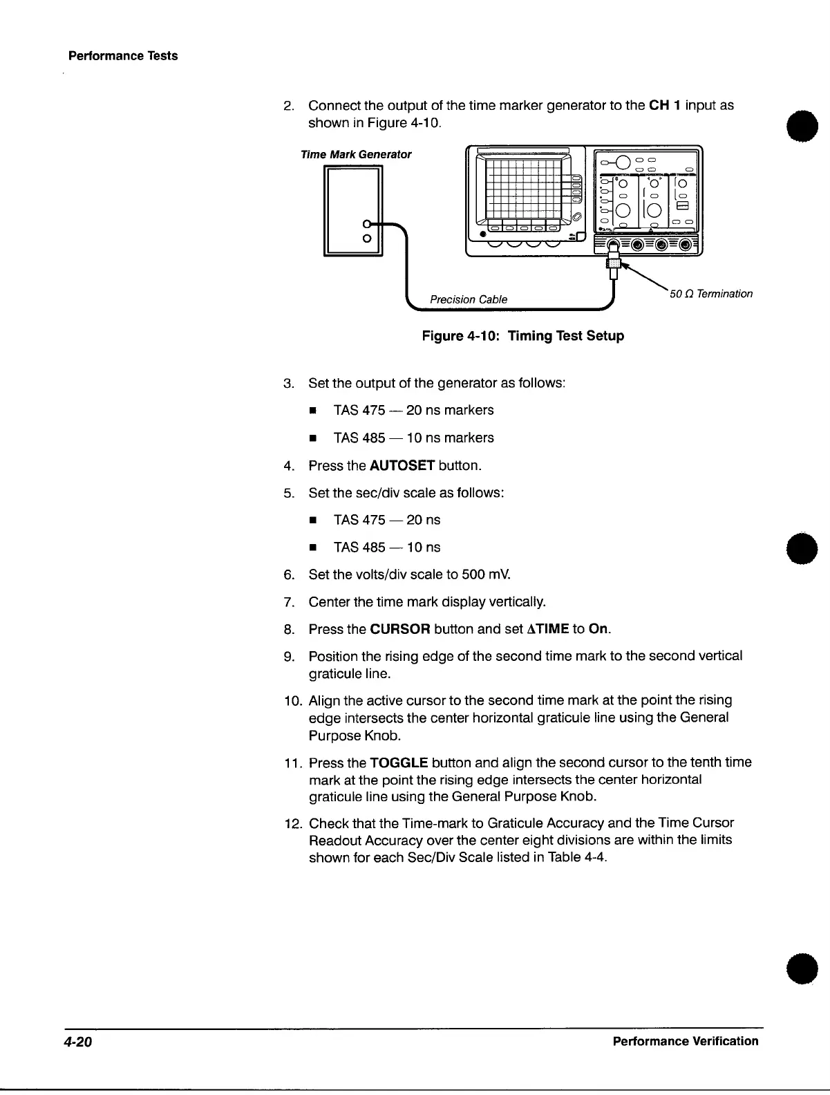
2.
Connect the output of the time marker generator to the CH 1 input
as
shown
in
Figure 4-10. •
Time
Mark
Generator
C)
C)
o
o
@
.00000
:;r
'_F'C7'C7~
0-()
00
00
·~.O
'0'
•
C)
r
C)
. 0 10
C)
r> r>
.....
C) C)
Pro"',/on Cabl.
~
50
Q T.",,/n,/loo
'-----------------~
Figure 4-10: Timing Test Setup
3.
Set the output of the generator
as
follows:
•
TAS
475 - 20 ns markers
•
TAS
485 - 10 ns markers
4.
Press the AUTOSET button.
5.
Set the sec/div scale
as
follows:
•
TAS
475 - 20
ns
•
TAS
485 - 10
ns
6.
Set the volts/div scale to 500
mY.
7.
Center the time mark display vertically.
8.
Press the CURSOR button and set ATIME to On.
9.
Position the rising edge of the second time mark to the second vertical
graticule line.
10. Align the active cursor to the second time mark at the pOint the rising
edge intersects the center horizontal graticule line using the General
Purpose Knob.
11.
Press the TOGGLE button and align the second cursor to the tenth time
mark at the point the rising edge intersects the center horizontal
graticule line using the General Purpose Knob.
12.
Check that the Time-mark to Graticule Accuracy and the Time Cursor
Readout Accuracy over the center eight divisions are within the limits
shown for each
Sec/Div Scale listed in Table
4-4.
Performance Verification
•
•
 Loading...

