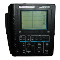
Functional Overview
2–14
THS710A, THS720A, THS730A & THS720P User Manual
Attach the Reference Leads Correctly
If you are using both of the oscilloscope channels, you must attach
the probe reference lead for each channel directly to your circuit.
These attachments are required because the oscilloscope channels
are electrically isolated; they do not share a common chassis
connection. Use the shortest possible reference lead with each probe
to maintain good signal fidelity. If you are also using the DMM, you
must also attach the DMM common lead to your circuit for the same
reason as above.
The probe reference lead presents a higher capacitive load to the
circuit-under-test than the probe tip. When taking a floating
measurement between two nodes of a circuit, attach the probe
reference lead to the lowest impedance or least dynamic of the two
nodes.
Beware of High Voltages
Understand the voltage ratings for the probes you are using and do
not exceed those ratings. Two ratings are important to know and
understand:
H The maximum measurement voltage from the probe tip to the
probe reference lead
H The maximum floating voltage from the probe reference lead to
earth ground
These two voltage ratings depend on the probe and your application.
Refer to Specifications beginning on page A–1 for more information.
WARNING. To prevent electrical shock, do not exceed the measure-
ment or floating voltage ratings for the oscilloscope input BNC
connector, probe tip, probe reference lead, DMM input connector, or
DMM lead.

 Loading...


