HD3G7 HD 3 Gb/s SDI Video Generator module
TRIGGER OUTPUT
. Allows you to select a line rate, frame rate, or the module
system clock as a trigger for an external instrument, such as an oscilloscope. (See
page 3-208, HD3G7 module TRIGGER OUTPUT submenu.)
SECONDARY OUTPUT. Use the left (◄)orright(►) arrow button to select
between a Test Signal or a Black output for the secondary (bottom) BNC
connector. (See page 3-208, HD3G7 module SECONDARY OUTPUT submenu.)
DIAGNOSTICS. Allows access to the outputs o f several diagnostics, shows
operation parameters for the module, and allows you to clear the counts of CRC
errors that are detected in the input signal. This menu provides status information
only and does not affect operating behavior. Select this menu item, and then press
the ENTER button to enter the DIAGNOSTICS submenu. (See page 3-209,
HD3G7 module DIAGNOSTICS submenu.)
CALIBRATION. Provides a variety of special signals to help measure amplitude
and rise time, and a llows you to adjust serial output amplitude. This menu is
accessible in factory mode only. (See page 3-211, HD3G7 module CALIBRATION
submenu.)
HD3G7 m odule
STATUS menu
Displays the instrument operating mode, output signal format, and output sample
structure. Examples of the STATUS display are shown below for each of the
operating modes (generator and converter).
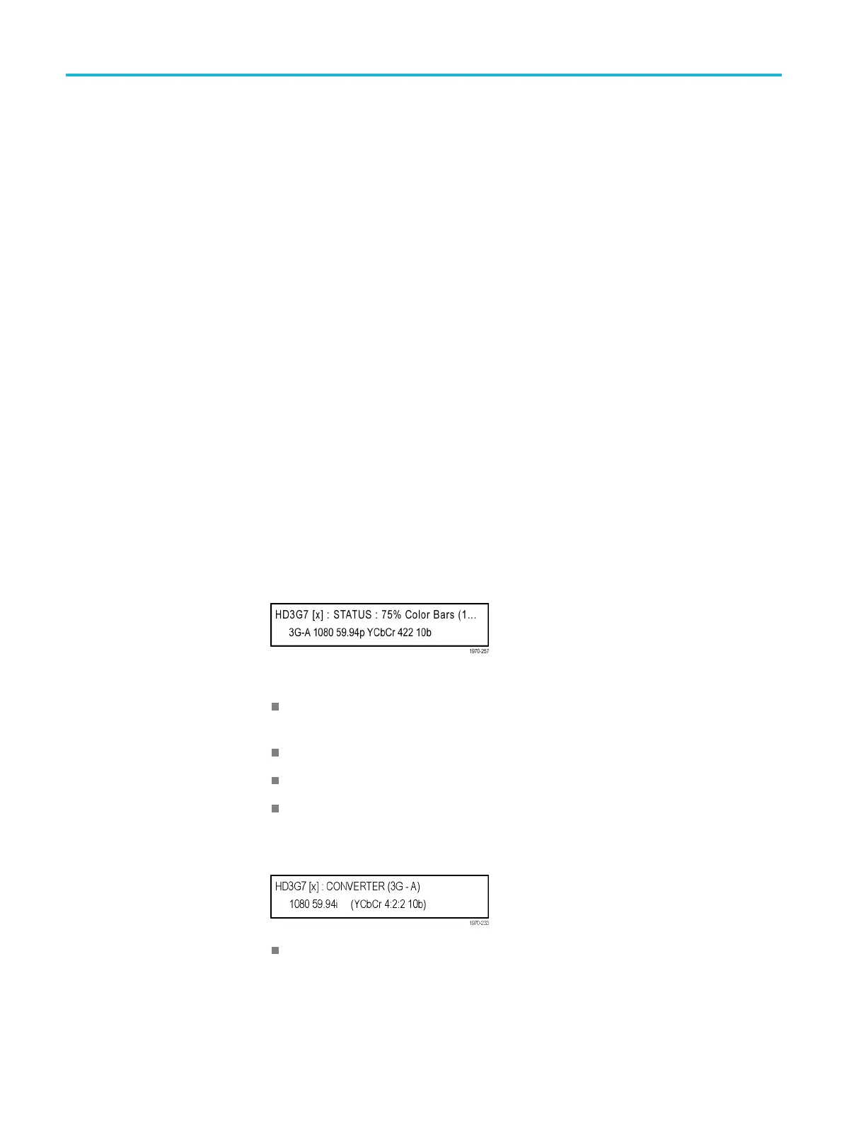
Generator M ode: The following figure shows an examp le STATUS display
when the module is i n generator mode.
Figure 3-85: HD3G7 module STATUS menu in generator mode
75% Color Bars (100% White): Indicates the name of the signal currently
being generated.
3G-A: Indicates the 3 Gb/s signal and the level currently being generated.
1080 59.94p: Indicates the output format.
YCbCr 4:2:2 10 bits: Indicates the output sampling structure.
Converter Mode: The following figure shows an example STATUS display when
the module is in the converter m ode.
Converter (3G-A): Indicates that the incoming HD SDI video stream is
being converted.
3–190 TG8000 Multiformat Test Signal Generator User Manual

 Loading...


