Aligna
®
4D User Manual
17 / 84
4.3 Positioning of Actuator and Detectors
In the following, we will discuss different setups to get the best setup of positions of the piezo-
controlled mirrors, the motorized mirror mounts, and the 4D detector system.
It is obvious that the detection of the beam movement has to be located BEHIND the actuators.
Otherwise a movement of the actuators cannot be observed by the detectors for pointing
correction in a closed servo loop.
In addition, it is obvious that the detectors should be located near the target (or experiment).
Then, all disturbances appearing at the path from the laser, passing maybe many folding
mirrors and optical elements, will be detected and compensated for.
It is NOT the case that both actuators should be located in the near of the experiment. The two
actuators may be located anywhere in the path up to the detectors. Of course, different posi-
tions have advantages and disadvantages, which will be discussed now:
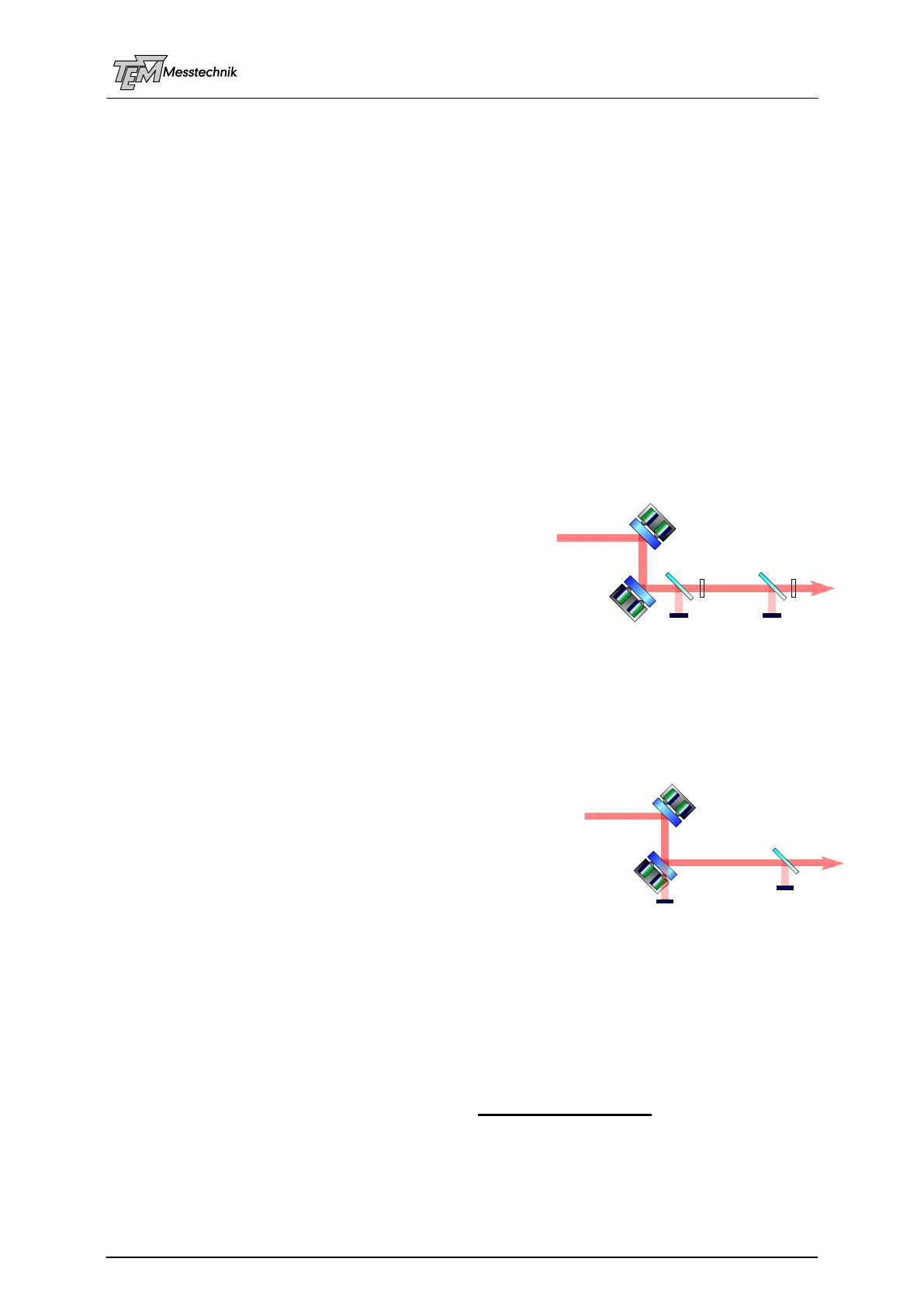
4.3.1 Setup 1: Two Beam Samplers
We will start with the perhaps most easy to understand setup:
Two mirrors are mounted at piezo-controlled mirror holders. Four piezos can control four de-
grees of freedom: Two translational (X, Y), two rotational
(, ).
Two 2D detectors represent two points of the laser beam.
The electronics keeps the beam exactly in the center of
both detectors. That means that two points of the beam
are fixed. Thus the complete beam will be fixed (as far
as no disturbance will happen BEHIND the detectors).
The position resolution is directly given by the position sensitivity of D1. A large distance be-
tween D1 and D2 leads to a high angle resolution. (The angle deviation is the difference of
both position deviations.) On the other hand, both detectors should be placed near by the
experiment. Therefore, a good compromise has to be found.
4.3.2 Setup 2: Second Mirror Acts as Beam Sampler
In the practical use it might be somewhat inconvenient to
use two beam samplers. We can use the second actuator
mirror as a beam sampler, because even very highly reflect-
ing mirrors will transmit a small amount of light. We only
need power in the order of some microwatts.
In this setup, detector D1 only observes the movement of
actuator A1. In fact, a movement of A2 will also cause a very
little beam movement at D1 due to beam shifting. However, this effect is negligible under
nearly all conditions. Detector D2, in contrast, observes a movement of A1 AND A2.
4.3.3 Problems with Beam Sampler Plates
A beam sampling glass plate (or a beam splitter cube), located in the main beam path, may
influence the beam quality, if the flatness, the transmission properties or the polishing is
non-perfect. High quality elements have to be used.
In most applications, beam sampler glass plates with parallel surfaces or beam splitter cubes
are NOT APPRECIATED: