Aligna
®
4D User Manual
19 / 84
4.3.5 Setup 4: Only One Beam Sampler Mirror
In a similar setup, a (nearly) non-polarizing 50% beam splitter
(plate or cube) is introduced behind a non-moved high reflecting
mirror, used for coupling out the test beam. This avoids the diffi-
culty of using the mirror at A2 both as mirror AND as beam sam-
pler. It leads to a smaller and more robust construction of A2. In
addition, it gives the advantage that the ratio of the intensities of
D1 and D2 only depends on the (known) properties of the detector
beam splitter, not on different transmissions of two HR mirrors.
Most of the problems with a beam sampler plate described before are not important here,
because the beam splitter is not located within the main beam path (dispersion, highest sur-
face quality and flatness, HQ AR coatings,...). Interference between surfaces has to be con-
sidered, as well.
4.3.6 Setup 5: Compact 4D Sensor "PSD 4D"
The distance between D1 and D2 determines the angle resolution. The introduction of optical
elements can shrink down the necessary size of the detection setup:
1. A lens can create a far field image at the detector D2: If D2 is located in the focal plane of
a lens; the detector is imaged to infinity. This detector will not register a (parallel) transla-
tion of the beam at all, as the lens laws show. It only registers angle movements. Therefore,
this would be a pure angle detector, while detector D1 acts as a pure position detector.
However, at a given detector size the angle resolution will
increase with increasing the focal length. The optimum
resolution is reached, if the focused spot diameter has
nearly the detector size.
2. For getting a compact design the beam can be folded by
mirrors back and forth, which leads to a very compact 4D
detector, as realized in the "PSD 4D" detector box, which
has the dimensions of only 80 x 80 x 40 mm.
The sketched setup here is the mostly used one with Aligna
®
applications
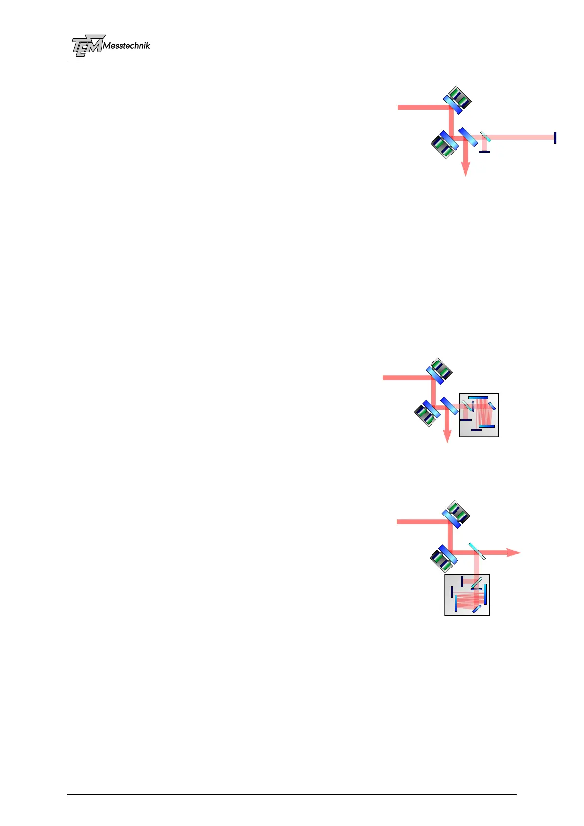
4.3.7 Setup 6: "PSD 4D" with Beam Sampler
Wedge Plate
Of course it is also possible to use a glass beam sampler for the
creation of the test beam to be lead into PSD 4D. The setup
shown here is often used for testing purposes, because in many
cases no change of a pre-existing optical setup is necessary. It
has to be clarified that the beam sampler plate does not cause
problems (too high losses, dependence on polarization, disper-
sion, interference).
Excessively high intensities at the detector have to be handled
by optical filters.