Aligna
®
4D User Manual
48 / 84
ever, too low signals (< 0.5 Volts, e.g) will degrade the precision (due to offsets, noise, etc.).
Excessively high intensity leads to non-linearities, and incorrect position measurement. (For
displaying the intensity in physical units (like mW, Watt, etc.) see below!)
"Dot Size" defines the size of the display dots at the XY scope. (Large dot sizes are used
when the computer screen is rather far away in the case of manual alignment at the experi-
mental table.)
"Radius" defines the radius of the displayed circle. This circle is used for different purposes,
displaying regulator ranges, target ranges for manual alignment, etc.
"Display" defines the displayed values. In many cases, this will be the position and angle
signals of the detectors. However, you can also observe the regulator outputs, the servo set
point values, and other variables (also depending on the hardware in use).
"BL speed" controls the request frequency of Kangoo for visualization of the displayed values.
It does not influence the (background) processing speed inside the µC! However, a too high
visualization speed will slow down the PC and the µC foreground speed (reaction to user
requests, etc.). Values between 3 Hz and 10 Hz are typical. (The maximum real request speed
also depends on the computer's speed and on the kind of values to be transmitted.)
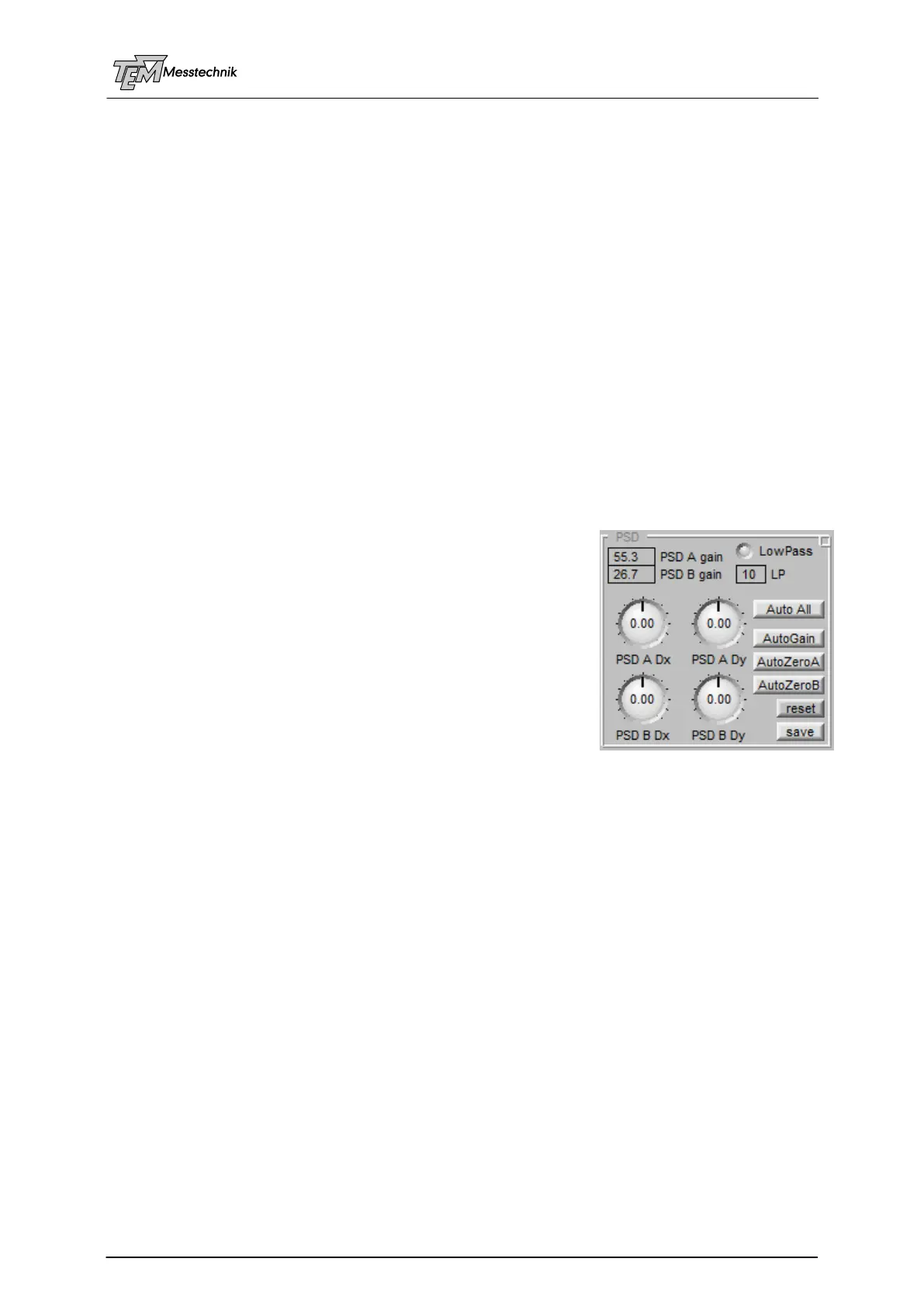
10.3.2 PSD Input Section
"PSD A gain" and "PSD B gain" control the programmable
gain values of the 8 transimpedance amplifiers inside the PSD
4D detectors.
The PSD gain values are displayed in "%": 100% indicates a
typical test beam intensity. The necessary values should be in
the range of 10%...300%. However, values up to 10000% are
possible (depending on the µC type). The higher the gain, the
stronger the sensitivity against environment light!
If the intensity is too high (gain < 10%) use neutral density
filters in the test beam path. (Otherwise, nonlinearities can
influence the measurement precision.)
If intensity is too weak, use a different beam sampler or different mirror coatings (please refer
to chapter on Beam Sampler Requirements, discussing possible problems of beam samplers
and filters, as interference effects and ghost reflexions.)
PLEASE NOTE: The PSD gain can be controlled over a very wide range of 1:4000! However,
if the test beam intensity is very high or very low, the system may even work properly, but the
performance and precision may be reduced.
The PSD offset values "PSD A Dx", "PSD A Dy", "PSD B Dx", "PSD B Dy", define the
position at the detectors, displayed as "0 / 0". If the offsets are "0" the mid position of the de-
tectors will be displayed as "0, 0, 0, 0".
This offset shift is achieved by different transimpedance gains of the quadruple amplifiers of
each detector (not by addition of an offset value. This leads to a much better linearity and
normalization precision). Therefore, the offset alignment is (nearly) equivalent to a mechanical
alignment of the detector positions ("virtual micrometer screws"), as long as the spot is not cut
by the detector's dimensions. (For the angle detector, which is (approx.) in the focus of a lens,
the spot at the detector ("A") will always be small. However, the position detector size ("B")
should not clip the (unfocused or partially focused) test beam too much. A little clipping is OK
in most cases: It leads to a non-linearity of the position measurement, which is not important in
most cases, because the beam is 4D stabilized to one fixed pointing. If however the spot size