Aligna
®
4D User Manual
51 / 84
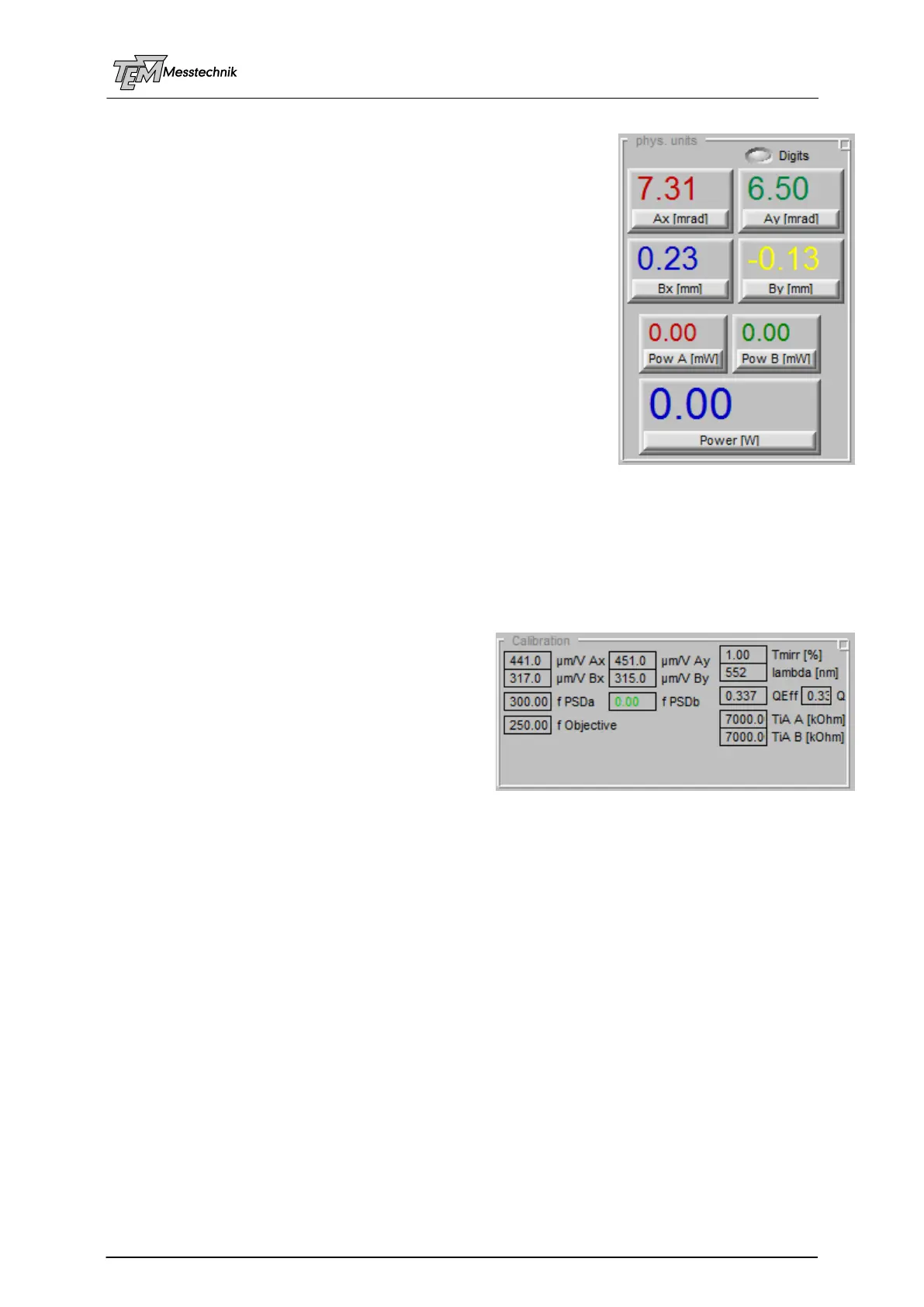
10.3.3 "Physical Units" Section
This section displays the measured pointing values as physical
units (in mm, µm, mrad, µrad, mW, Watts, etc.) in numerical
displays.
The display depends on the selected units (see Section "PSD
input"). The angle values may be displayed in [mrad] (0.001
mrad means 1 µrad), the position values are displayed in [mm]
(0.001 mm = 1 µm, 0.0001 mm = 100 nm, depending on the
selected resolution.)
The measured angle of the beam can also be displayed as µm
spot translation in the target plane, depending on the focal length
of the focusing optics in use. (For instance, an angle displace-
ment of 10 µrad, using a focusing optics of 250 mm, will cause a
spot displacement of 2.5 µm in the target plane.)
These parameters are defined in section "Calibration"
The switch "Digits" defines the displayed number of digits. If the
spot-to spot fluctuations of a pulsed laser (which cannot be compensated for by principle) will
fluctuate by 10 µm, for example, the display is less confusing if the displayed values are
rounded to 10 µm. (Depending on the application the display will be switched between 2 and 3
decimal digits. Higher resolution is possible, even using short focal lengths of the target objec-
tive.)
10.3.4 "Calibration" Section
This section contains the calibration parameters
of the individual opto-mechanical setup. (These
parameters have to be set ONCE. They should
be stored in the individual "User Script" for being
present even after choosing "Default Values".
After the correct setting, this section will be
shrunk, because it is no longer needed).
"µm/V Ax" ... "µm/V By" define the translation between measured Volts to mm at the detector.
These values can be trimmed easily, if the detector or the beam is shifted by a known dis-
placement (position and angle). Then the parameters are scrolled, until the correct physical
value (in [mm], or [mrad]) is displayed in the "physical units" section.
For this procedure, TEM provides calibrated elements (40x40x40 mm cubes including glass
plates). The "Position Calibration Cube" contains a (very parallel) glass plate at an aligned
angle, which introduces a well defined position displacement (for example 2 mm).
The "Angle Calibration Cube" contains a wedged glass plate, which introduces a well defined
angle displacement (for example 1 mrad).
However, the user can realize own calibration tools. The detector can be set to a calibrated
(manual or motorized) translation stage. The real displacement can be taken from a microme-
ter screw, or from the motorized stage.
A (small) angle displacement can be realized by moving a conventional mirror mount, watch-
ing the spot at a long distance (many meters at the wall).
"f PSD A" and "f PSD B" are used to calculate the measured angle movement from the
measured position movement at an angle detector. (For example: an angle movement of
1 mrad will cause a spot movement of 300 µm at the angle detector chip in the focal plane of a
300 mm lens). (A value of "0" indicates "no lens", which is typical for the position detector "B",