Aligna
®
4D User Manual
28 / 84
In the next step this tube entrance beam position is held fixed, and by means of a suitable
OCL matrix the angle of the beam is scanned in X and Y (orthogonally or in a special search
spiral shape), until a detector at the outlet of the tube is hit. This detector normally is a 2D or
4D PSD. (Alternatively, another AimPD of the next part beam is used. So many part beam
sections can be aligned automatically, fully hands-off.)
If this PSD is hit, M1 is stabilized with rather high servo bandwidth to the center of this PSD.
Due to the long BLT the mirrors at the laser hutch (or the laser table) do not really have an
influence to the beam angle at the experimental hutch (or the experimental table), but just to
the beam position in the experimental hutch. The angle is defined (and "fixed") by the axis of
the BLT.
So the described stabilization is just a 2D stabilization. Only one of both motorized mirror
mounts (MMM) has to be a fast 2D actuator (MoPiA). The second one is just used for "coarse"
alignment (hitting the tube entrance). Therefore, requirements on speed and resolution are low.
For the second actuator a motorized actuated MMM (MoA) is sufficient.
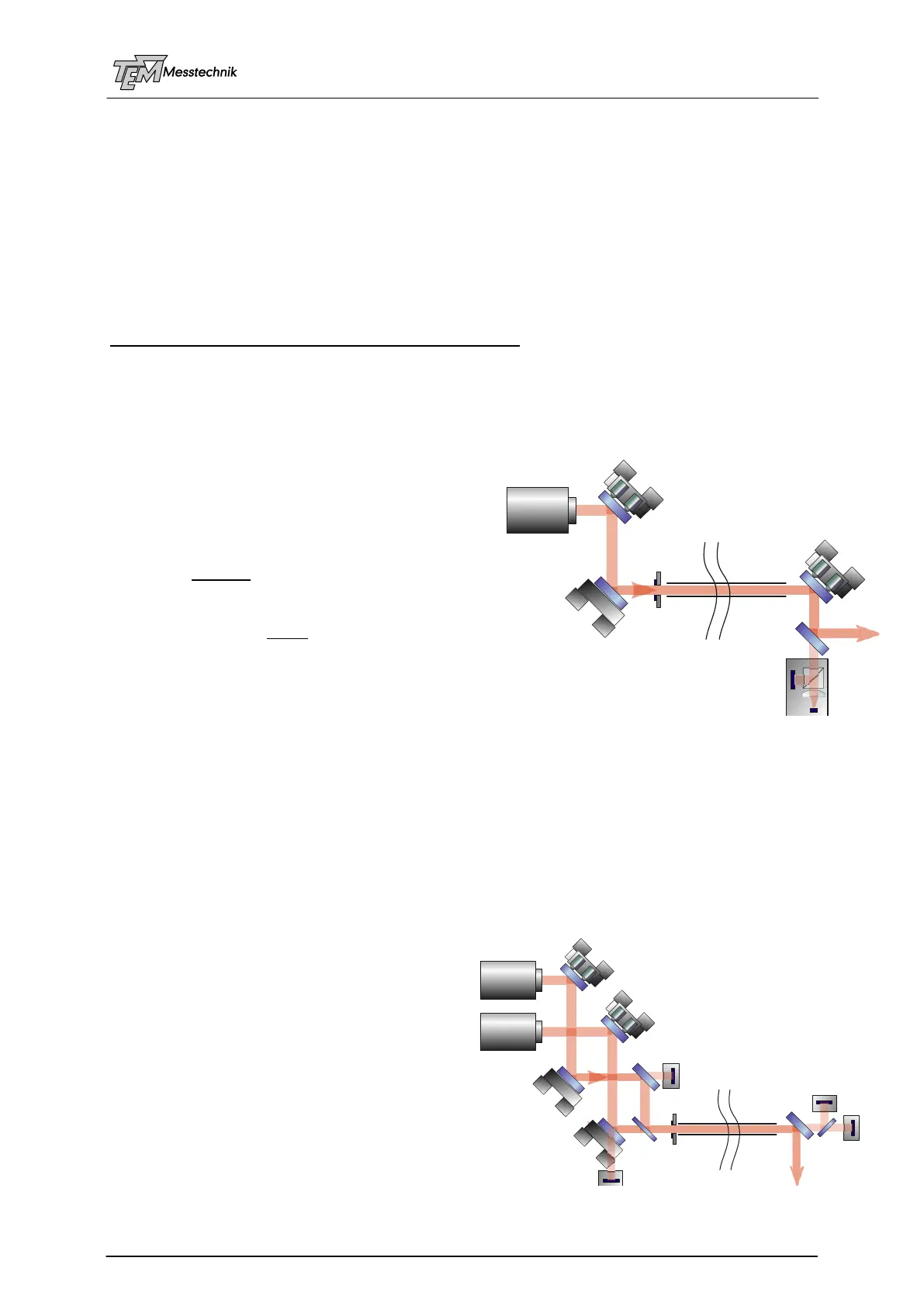
5.6 Auto-Alignment and 4D stabilization
In a large laser setup with long beam lines in
reality often many more optical components (mir-
rors, lenses, telescopes,…) are in the optical path
(for simplicity not sketched here). All of these
components may drift, vibrate, fluctuate, move,…
The beam position at the target table is aligned
and stabilized by M1 and M2 in the manner, de-
scribed in the former chapter. However also (or in
particular) the beam angle, hitting the target (or
the targeting objective) is very sensitive, and has
to be stabilized as well.
In this case another active mirror (M3), located in
the experimental hutch (at the experiment table) is
used, as well as a 4D (instead of a 2D) detector, which measures simultaneously and inde-
pendent from each other Angle X/Y and Position X/Y. Thus, the beam is automatically aligned
and kept along the long beam line tube, position AND angle are stabilized with respect to the
target. (This setup is one of the Aligna standard setups, it is described later in deeper detail.)
5.7 Overlaying Two or More Laser Beams Independently
In many experimental setups it is necessary to overlay two or more laser beams (with different
wavelengths, sometimes with different polarization, with different pulse timing, maybe cw and
pulsed, etc.) at exact one common optical axis.
Sometimes all beams have to go through the
same long beam line tube.
The beams are often combined by help of a
dielectric beam combiner (DBC).
All methods, previously described, can be
transferred to two or several beams. The
additional task is to place the detectors and
add some dielectric beam separators (DBS) in
the detector path (or a polarization cube,
interference filters, etc.), so each detector only
observes the related laser beam.
M3
4D System
with AutoAlignment
M1
M2
MoA
MoPiA
MoPiA
BeamLine
Tube
AimPD
Laser
BSM
PSD 4D
Overlaying of Two
Independent Beams
M1A
M1B
M2A
M2B
MoA
MoA
MoPiA
MoPiA
AimPD
DBC DBS
BeamLine
Tube
PSD 2D AA
PSD 2D AB
PSD 2D BA
PSD 2D BB
Laser A
Laser B