Aligna
®
4D User Manual
20 / 84
What is the Best Setup? Some Selection Rules
All of the described setups can be realized with the Aligna
®
4D (using PSD 2D or PSD 4D,
different types of beam samplers). The user may decide which fits best to his application.
However, there are some rules for selection:
4.3.8 Distance between A1 and A2
The distance between A1 and A2 defines the possible compensation of the beam translation
movement, while the possible rotation movement is independent on this distance.
Of course, in most cases a small and compact design is appreciated. What are the criteria?
If there is a large distance between the laser and the experiment, even small angle move-
ments are translated into large transversal movements. In these cases, a large distance be-
tween the mirrors A1 and A2 is recommended. If the distance from the laser to the experiment
is many meters, the optical path distance A1 to A2 should be 50 cm or more.
The standard actuators BeamScan 2D can move the mirror by an angle range of 2.3 mrad in
X and Y direction. That means with a distance between A1 and A2 of 1 meter a beam dis-
placement of up to over ± 2 mm can be compensated. This is quite sufficient for most applica-
tions.
One mm or more will only be necessary with very long laser beam distances of over 5…10
meters, depending on environmental properties, or with the use of delay lines and other mov-
ing optics. In fact, it is not easy and takes some time to align a delay line to much better than
some 100 microns of beam shift (depending on the moved rail length of course).
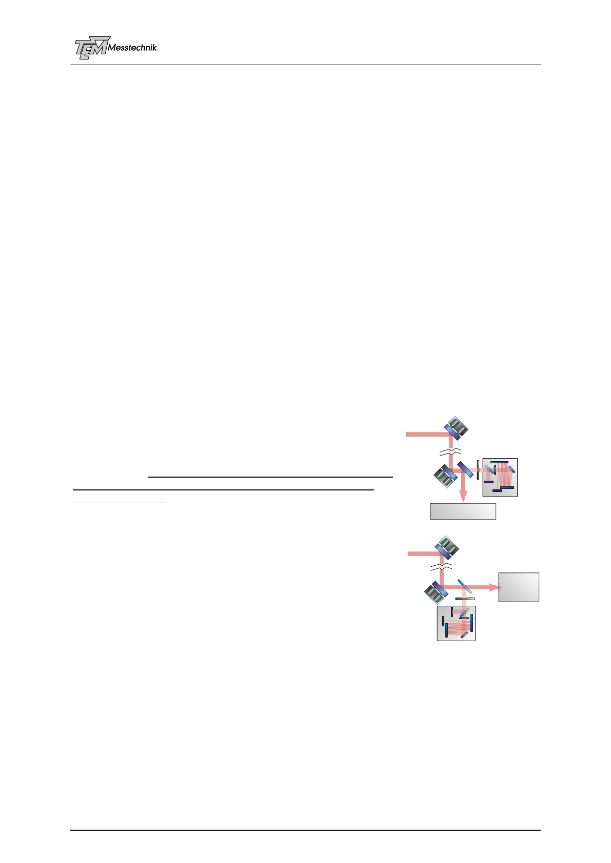
4.3.9 Position of the Detector(s)
The 4D detection should be located close to the experiment,
because only disturbances in the path BEFORE the detector can
be detected, and thus can be eliminated.
Even if a large variety of positions and distances can be handled
by Aligna
®
4D the best position of the 4D detector (or the first of
the two PSD 2Ds) is as close as possible behind the second
actuator mirror A2. (Of course, the necessary beam sam-
plers/mirrors and maybe filters for adjusting the detection beam
power have to be between A2 and the detector.)
In this case, the four servo loops can mostly be separated from
each other. This leads to a more stable and robust locking be-
havior.
D1
D2
PSD 4D
Experiment
Experi-
ment
A1
A1
A2
A2
Filter
Filter
D1
D2
PSD 4D