Aligna
®
4D User Manual
47 / 84
10.3 Some Common Sections
In many application-specific configurations (graphical user interface), there will be identical or
at least similar sections, as shown in the "Basic" configuration; some of them are described
now:
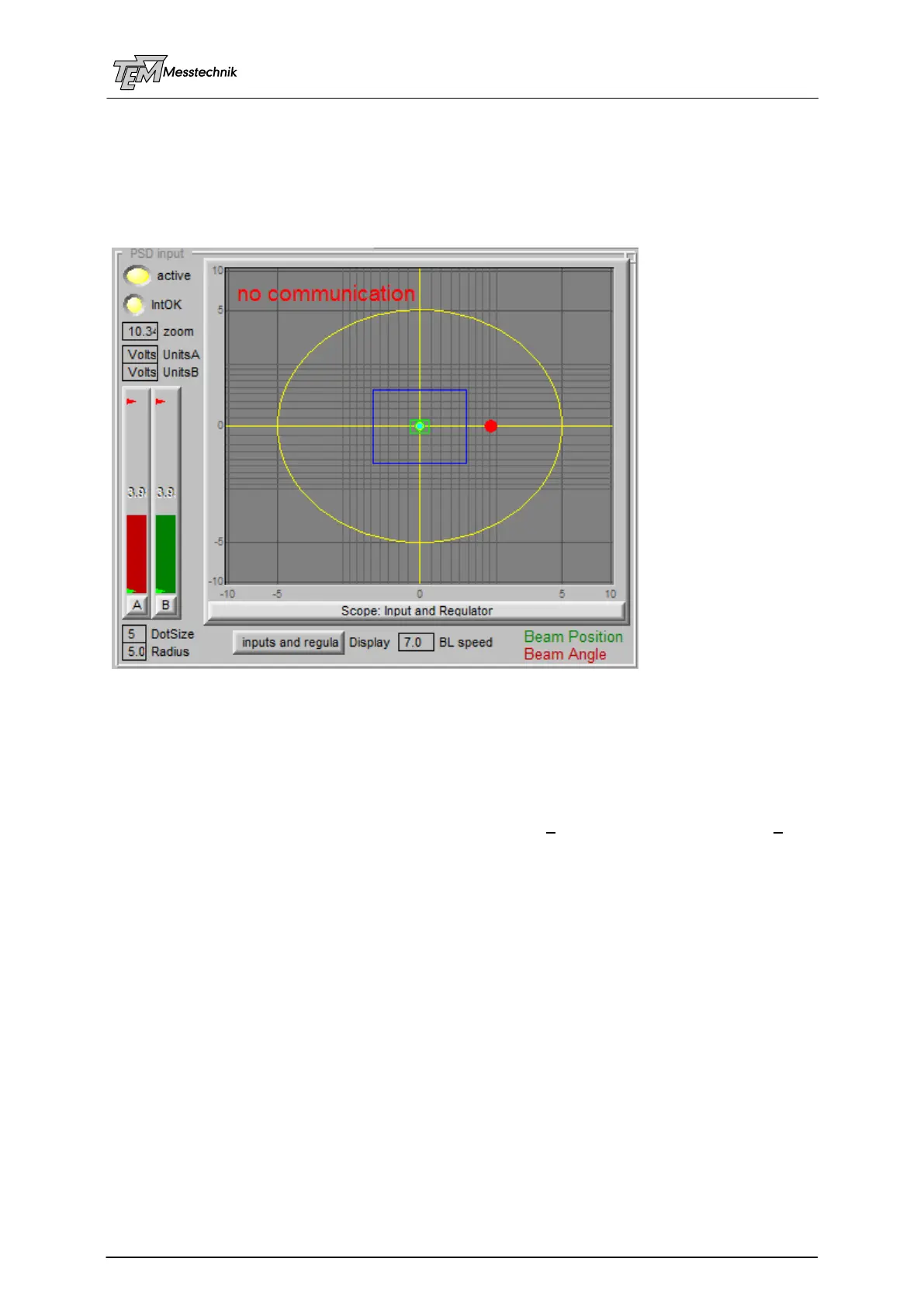
10.3.1 PSD Input Section
The "active" switch enables or disables the background requests of the actual position and
intensity values. It should be switched ON (yellow) normally. It is switched OFF for some
measurement procedures to avoide information collision. In most cases this is done
automatically, thus this switch may be hidden in some configurations.
"zoom" defines the displayed range. Depending on the displayed units (see below), standard
is +/- 10 Volts, which is the range of the basic PSD and servo signals.
"UnitsA" and "UnitsB" define the displayed units for the angle detector "A" and for the beam
position detector (B). This may be "Volts" (basic signals), calculated physical units like "mm"
(used for position and angle detector), "mrad", "deg" (=degree) "arc min", "arc sec", (normally
used for angle detector), "mmTarget" (mm at Target position, also used for angle detector). In
some applications, both detectors A and B are used for position or for angle measurement.
Thus, all combinations are possible. (For calculation of these units, some parameters are
needed, defined in section "calibration", like focal length of the PSD lens, of the target focusing
lens, etc.)
"IntOK" (Intensity OK) indicates valid intensity levels at all used detectors. (Regulation can
only be switched on, if intensity is in the OK range (yellow). Normally the OK range is defined
being between 0.5 Volts ("min Intens") and 5 Volts ("max Intens"). These min/max values are
indicated as small green and red arrows in the intensity bars. They are defined in the "Thresh-
olds" section. If intensity is above "max Intens", lamp IntOK will be red. In this case an overrid-
ing of the internal signal amplifiers may lead to incorrect position measurements. (A damage of
the PSD chips will occur much (many orders of magnitude) later, depending on the pulse
duration and of the focusing. See PSD description.)
Bar graphs "A" and "B" display signal strength at the position sensitive detectors (PSD) in
use. The intensity signals are influenced by the PSD gain values (see section "PSD"). The
units are Volts. The intensity signals do not directly influence the position measurement. How-