Aligna
®
4D User Manual
57 / 84
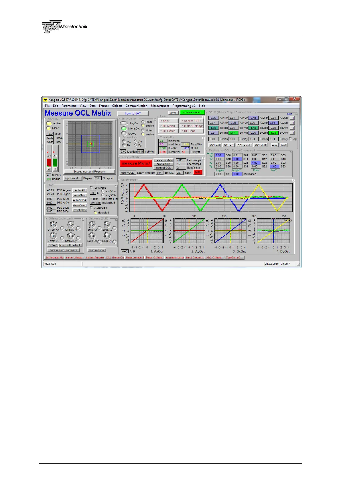
10.3.10 Alignment of the "OCLM" Matrix
(Output CrossLink Matrix of Motorized Actuators)
The OCL matrix (both OCLP for piezos and OCLM for motors) can be aligned manually (by
changing the matrix elements) or -much more convenient and more precise- by automatic
OCL learning procedures.
Go to configuration “Measure OCL Matrix” (e.g. from the “BeamLock Menu” configuration)
This configuration gives you access to most of Aligna's parameters.
In the following, we will describe the basic steps:
coarse manual alignment of the opto-mechanical setup
learning the motor's OCL ("OCLM")
starting the motor servos, optimizing the motor servo "total gain"
If you have a system including motorized AND piezo servos, now
learning the piezo OCL ("OCLP")
starting the piezo servos
optional: optimizing the piezo servo parameters
As mentioned before, it is STRONGLY RECOMMENDED to start with a simple test setup
(visible (!) laser pointer, the two actuator mirrors, the 4D detector) for learning the usage, to
play with the parameters, and to get some experience with the signals and the system behav-
ior.
Normally your system has been delivered with the "Plug'n Play Kit", which includes all Aligna
components at acrylic base plates, a laser, the mirror mounts with actuators (motorized and/or
piezo), including mirrors (aluminium coating for testing purposes only), the 4D detector (differ-
ent types possible), a beam sampler plate (for testing only!), two apertures, representing your
experimental setup.