Aligna
®
4D User Manual
58 / 84
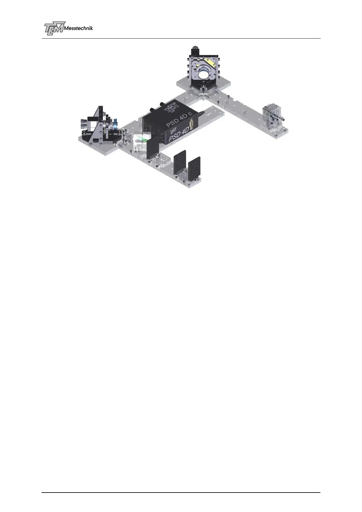
Aligna Plug'n Play Kit
Prepare the system as described in "Setting-up a Test System"
Cable Connections
Switch on the Aligna
®
rack case
If your test laser can be switched between cw and pulsed, start with cw mode
Installation and start of the visualization software "Kangoo"; start Kangoo, choose configu-
ration "Aligna / BeamLock Basic Use"
Check communication between the PC and the Aligna microcontroller (simplest way: use a
serial interface, COM1. In the case of USB you have to check the "virtual COM port" num-
ber, see USB description)
Coarse pre-alignment of the opto-mechanical setup (is done, if you got the Plug'nPlay Kit)
Set detector sensitivity (manually turning "PSD A gain", "PSD B gain", or by clicking "auto-
Gain")
Normally we deliver your system with pre-aligned parameters. Therefore, the OCLs will fit for
the test setup as displayed. If you have got the "Plug'n Play Kit", even the laser dependent
parameters (PSD gain A and B) will fit.
If you start from scratch, you can choose button “OCL dflt” (“set OCL matrix to default values”).
This will set all values valid for a typical setup (distance of mirrors M1-M2 approx 22 cm, dis-
tance M2 to detector “PSDi 4D” approx 10 cm). However, it depends on the type of actuators
(Aligna 40, Aligna 60, Aligna AddOns,...) and type of PSD. Thus, sign and gain values may be
wrong.
If your system is completely different from the test setup you can also start with the unity ma-
trix (“OCL = 1”), that means Ax goes to motor 1x, Ay goes to motor 1y, Bx goes to 2x, By to 2y.
This is a completely wrong matrix, but the system will learn from it rather easily.
IMPORTANT: If the laser in use is a cw laser (or the Plug'nPlay-Kit test laser in cw mode) or a
pulsed laser (or the test laser in pulsed mode) the parameter "cw/pulsed" (section PSD") has
to be selected correctly as "cw" or "pulsed", and the (approx) RepRate [Hz] has to be set.
Otherwise, a correct position and intensity measurement is not possible!