Aligna
®
4D User Manual
59 / 84
Choose "Learn Program: Motor OCL" (The system will learn the OCL for the motor servos)
(Section "OCLM (Motors Output CrollLink Matrix" will be visible)
Click “measure Matrix!”, which starts the learning procedure:
If "autoGZ" is set to "Z+G autoZero and autoGain before learning" is set, first the system will
perform a “PSD AutoAll” procedure (automatic alignment of PSD gains and alignment of the
offsets), to see the actual beam pointing approx. at the position 0,0,0,0.
Then all four channels (Ax, Ay, Bx, By) will scan all actuators, using the actual OCLM matrix.
You can watch the red and the green dot. The better the OCL fits to the real setup, the more
independent the dots will move (to the right, to the left, up, and down, back again to the mid
position, both for channels A and B).
The goal is to find an OCL(M) matrix, so the Total Loop Matrix (behavior of the opto-
mechanical setup "System Matrix", multiplied with the OCL Matrix) will be the unity matrix.
That means:
For example: Changing of the parameter “Bx” (beam position x) is seen at the detectors as “Bx”
movement only, no other movements (no position Y, no angle X, no angle Y). Similarly for the
other parameters “Ax, Ay, By”. This means, all channels are (as good as possible) independ-
ent from each other, they do not influence each other, and a fast and safe servo work is possi-
ble. The creation of this independency is called “orthogonalization”.
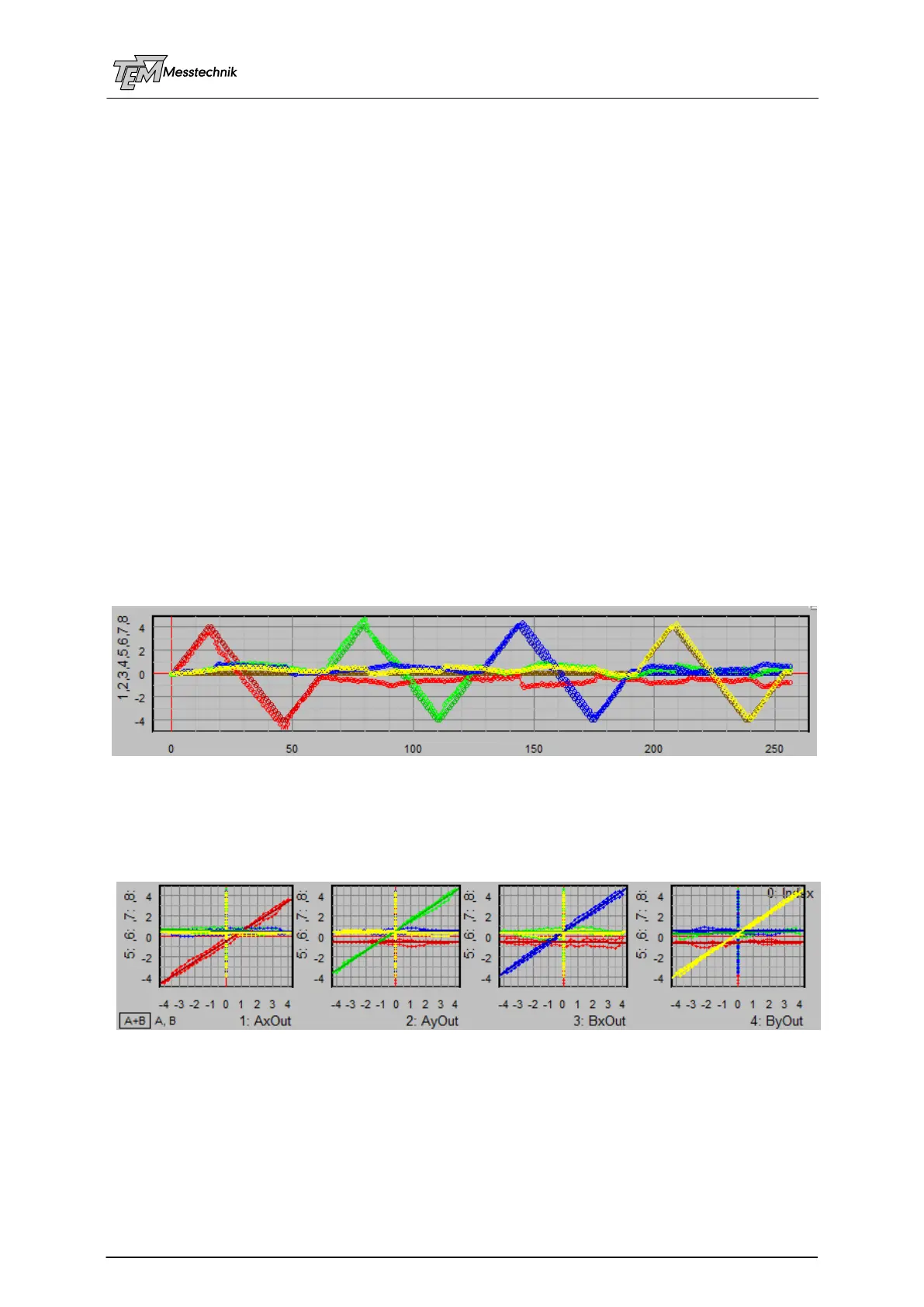
In the measurement data coordinate systems you will see four coloured traces with the (trian-
gle shaped) set values (Ax: red, Ay: green, Bx: blue, By: yellow), and four traces with the
measured values (Ax: dark red, Ay: dark green, Bx: dark blue, By: brown=dark yellow)
Set values and measured values
You can also see the same data in the correlation data frames: The goal is to reach a diagonal
(red, green, blue, yellow) in each four correlation coordinate systems (Set values Ax, are
identical with measured values Ax, etc.). The other traces should be horizontal or vertical lines,
close to the axes (no influence of Ax to Ay, Bx, By, etc.)
Four diagonals: red (Ax), green (Ay), blue (Bx), yellow (By)
If you look precisely, you can also observe the mechanical hysteresis between the up-scan
and the down-scan. If this hysteresis is much larger than displayed here (>10%) there is some-
thing wrong with the mechanics: Mirror mounts at the mechanical limits, or cables touch actua-
tor knobs, or similar.
After the measurement, the Total Matrix is calculated and displayed: