Aligna
®
4D User Manual
52 / 84
using "UnitsB = mm".) In some applications, however, both detectors A and B are used for
angle measurement. In this case, "f PSDb" has to be set to the correct focal length of lens B.
"f Objective" corresponds to the focal length of the target focusing objective. Thus, the meas-
ured angle movement will be transformed into a spot movement in the target plane. Displaying
the angle is often less intuitive than the spot movement in the target plane.
The following parameters are used to calculate the real laser power (for monitoring/logging
purposes).
"Tmirr [%]" is used to calculate the laser power from the measured test beam power. It de-
fines the part of light put from the main beam into the test beam. This may be the transmission
of a highly reflecting mirror (typ. 0.1%), or the reflectivity of a beam sampling plate (typ.
0.2...4%) or even a beam splitting cube (typ. 50%). If "Tmirr" is chosen as 100% "Power" will
display the test beam power.
PLEASE NOTE: The transmission or the reflection of optical components can be STRONGLY
dependent on the polarization angle between the laser beam and the optical component's
orientation.
"lambda [nm]" defines the used laser wavelength. From this the calibration curve device
"QEff" calculates the actual quantum efficiency of the PSD in use.
By means of the transimpedance gain factors "TiA A" and "TiA B" and the chosen PSD gain
settings, the microcontroller can calculate the test beam power at both detectors.
In most cases, you will align "Tmirr" as follows:
Align "PSD gains" so both intensities are OK (some Volts). Measure the real laser power with
a suitable power meter. Select the wavelength "lambda [nm]" correctly.
Turn "Tmirr" (with the mouse wheel) until the correct laser power is displayed at the device
"Power".
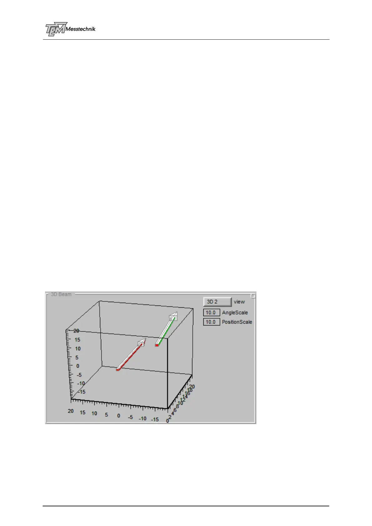
10.3.5 "3D Beam" Section
In the section "3D Beam" you can watch the beam pointing in a 3D frame. You can rotate the
frame or choose predefined points of view to get the best overview of the beam movement.
(The red arrow indicates the "reference beam", normally position X/Y = 0/0, angle X/Y= 0/0)
By means of the scaling parameters, both angle and position can be "blown up" for best view.