Aligna
®
4D User Manual
29 / 84
The "angle" detectors of beams "A" and "B", "PSD AA" and "PSD AB", will be located close to
the target, while the "BeamPosition" detectors "PSD BA" and "PSD BB" are located near the
lasers. They are also used for automatic combining alignment, in cooperation with an "AimPD",
acting as a conjunct "electronical iris". If necessary, additional AimPDs can be inserted at
critical points of the beam path, so all beams go exactly the same way.
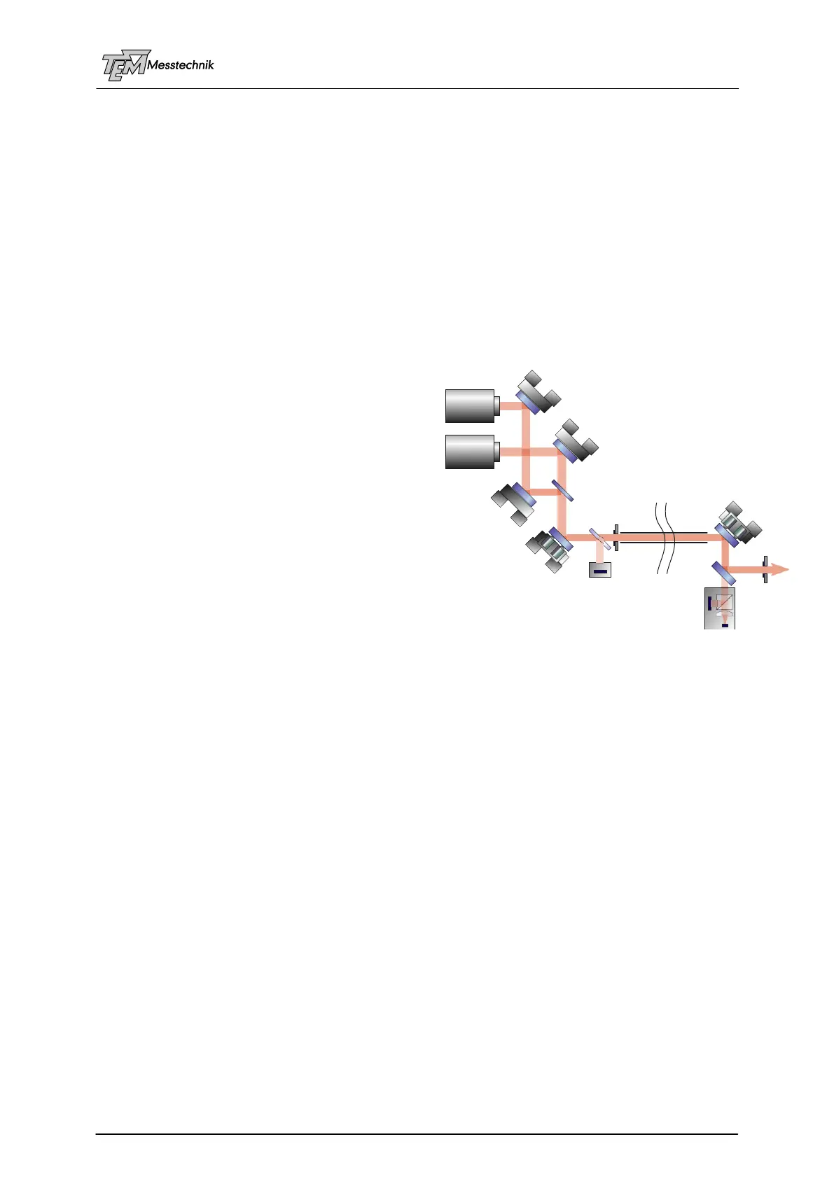
5.8 Overlaying Two Laser Beams, Commonly Stabilized Path
Separating all beams and using complete independent detectors and motorized and piezo-
actuators for all beam is a certain effort, especially for many beams. Often the relative drift of
the lasers with respect to each other is small, compared to the beam pointing fluctuation
caused by the long beam path. It is not always necessary, to stabilize all beams completely
independently with full servo speed in 4D. Often it is sufficient to overlay all beams (just rather
slowly) with the motorized mirror mounts, and stabilize the common beam path with help of
(just two) fast piezo-based mirrors.
A certain problem when using several beams
with very different wavelengths and/or very
different power levels in one path is the beam
sampling to observe all lasers simultaneously
with one detector. Beam sampling due to leak of
a HR mirror is rather difficult, because the leak
of one mirror will be very different for the several
wavelengths, also strongly dependent on polari-
zation, etc.
We also can use motorized filter wheels and/or
motorized flip mirrors to get suitable signal
strengths using the same detector for all wave-
lengths (just one at a time).
Following tasks can be separated:
Automatic overlaying the beams at the combining mirror (or at any other point close to the
laser sources) (with motorized mirror mounts M1A, M2A and M1B, M2B, regarding a mo-
torized electronic iris AimPD1, or the optional PSD 2D)
Automatic overlaying the beams in the near of the target (with motorized mirror mounts
M1A, M2B, M1B, M2B, regarding a motorized electronic iris AimPD2)
4D stabilizing just one beam, (with piezo actuators MoPiA M2B and M3) to avoid drifts and
air fluctuations along the common beam path (using a PSD4D suitable to one of the wave-
lengths). All beams go the same path, so all beams will be stabilized regarding the drifts
and disturbances at the common path.
The overlaying can be observed and -if necessary- repeated from time to time. This can be
done automatically by help of one or several AimPDs ("electronical irises").
For this check of overlaying the beams are blocked (manually or by electrical shutters), just
one beam is enabled at a time. The electronical irises (or wavelength-depending flip mirrors) in
the common beam path close (depending on the former defined beam size). Each beam is
automatically aligned regarding the irises. Then the irises are opened and all beams are ena-
bled by the blocks or shutters. The fast 4D stabilization for one of the beams is enabled, the
other beams are stabilized as well at the same path.
Optionally, a PSD (for one or several beams/wavelengths) and a beam sampler plate (BSP)
can be installed at the laser table. In this case, a continuous observation (not from time to time)
of the beam position at the laser table is possible.
(optional PSD 2D)
Overlaying of Two Beams
Fast Stabilization of One Beam
M1A
M1B
M2A
M2B
MoA
MoA
MoA
MoPiA
AimPD 1
AimPD 2
DBC
BSP
BeamLine
Tube
Laser A
Laser B
M3
MoPiA
BSM
PSD 4D