Aligna
®
4D User Manual
45 / 84
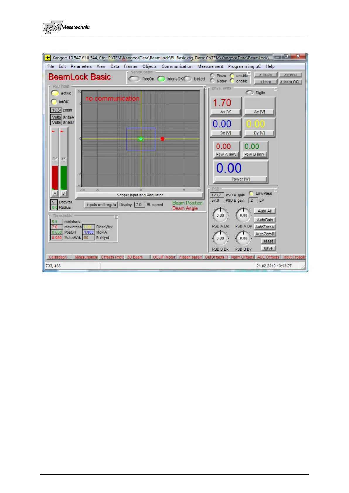
10.2.2 Configuration "BeamLock Basic"
Configuration "BeamLock Basic" is for general use of Aligna
®
systems or even PSD systems
(without actor control or servo loops)
The following sections are mainly used: (unneeded sections are "shrunk", indicated as a but-
ton at the window bottom)
The section "PSD input" shows the actual position and intensity values (and other values,
like regulator outputs, e.g., if selected.)
The section "PSD" controls the sensitivity of the transimpedance amplifiers (located in
the PSD housings). They correspond to the applied detector intensity at the angle detector
(PSD A) and the beam position detector (PSD B). The eight amplifiers (four for each PSD)
are controlled by multiplying DACs (MDACs) (For details see below.).
The exact fine X/Y position of the detectors is not aligned by mechanical micrometer
screws, but by “virtual micrometer screws”, namely the relative sensitivities of the quadruple
transimpedance amplifiers of each PSD. These "virtual micrometer screws" (it is not the
same as a simple offset, as explained in the PSD description!) are called "PSD A
Dx"..."PSD B Dy")
The Input CrossLink Matrix (ICL) aligns the “virtual position” of the detectors: A pure
angle detector, e.g., has to be positioned exactly in the focal plane of an optical lens, for be-
ing insensitive to XY parallel translation beam movements). This requires precise mechani-
cal alignment components and a sensitive alignment procedure. If, however, two PSDs are
present, one mostly watching angle, one mostly watching position, by help of mixing the
signals a pure angle and a pure position signal can be calculated without the need of me-
chanical alignment. This is done by the ICL Matrix.