Aligna
®
4D User Manual
31 / 84
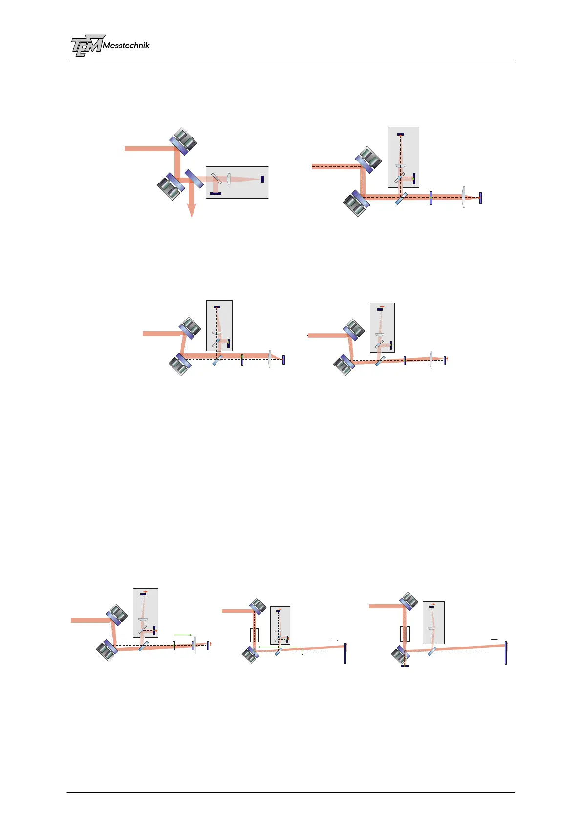
5.10 Comparison of some Setups
As a comparison, some basic setups are discussed now.
Beam sampler types of 4D detector setups:
High reflecting mirror as beam sampler Weakly reflecting beam sampler plate
Defined displacements due to changing or scanning the angle or position servo setpoints;
the beam is fixed at one detector, scanned relative to the other one.
(Here displayed with beam sampler plate, works with HR sampler mirror as well):
Position displacement Angle displacement
In violet: virtual positions A' and B' of Angle detector A and BeamPosition detector B
Shifting the virtual position of the B detector due to the Input CrossLink Matrix (ICL):
This shifting of the virtual detector position, or the rotation point of angle movement is done by
adding or subtracting an amount of angle signal Ax, Ay to position signals Bx, By in the ICL.)
It allows the scanning of the beam angle (and so the target spot position) without moving the
beam position at sensitive optical elements, like objectives, telescopes, frequency doubler
crystals, amplifiers, etc.
In the first example, the entrance pupil of an objective shall be hit exactly, while moving the
target spot position. In the second example, the optical axis of a telescope (or crystal, amplifier,
modulator,…) shall be hit, while stabilizing (or scanning) the output beam angle. (The green
arrow indicates the shift of the virtual position of the B detector, which defines the rotation
point of the angle scan.)
Fixing the beam position at an entrance pupil, or at a telescope axis for scanning the angle
M1
M2
BS
Objective
Target
B
A
B‘
A‘
M1
M2
BS
Setpoint A = 0 [µrad]
Position Displacement
--> Angle Displacement at Target
Setpoint B = 20 [µm]
B
A
B‘
A‘
Angle Displacement
--> Position Displacement at Target
Setpoint A = 20 [µrad]
Setpoint B = 0 [µm]
M1
M2
BS
B
A
B‘ A‘
--> Position Displacement at Target
without movement in Entrance Pupil
Shift of Virtual Position of B Detector
and of Angle Rotation Point
into Entrance Pupil of Objective
(by Input CrossLink Matrix, ICL)
Setpoint A = 20 [µrad]
Setpoint B = 0 [µm]
M1
M2
BS
B
A
B‘ B‘ A‘
--> Angle Displacement Scans
without Movement at Optical Elements along the Path
(Telescope, e.g.)
Shift of Virtual Position of B Detector
and of Angle Rotation Point
into Second Active Mirror
(by Input CrossLink Matrix, ICL)
Setpoint A = 20 [µrad]
Setpoint B = 0 [µm]
∞
M1
M2
BS
B
A
B‘
B‘
A‘
It is equivalent to the following setup,
in which the B detector is located directly behind M2.
So M1 is stabilizing the Beam Position at M2,
while M2 is stabilizing or scanning the output angle,
however, without the need of a second sampling!
Setpoint A = 20 [µrad]
Setpoint B = 0 [µm]
∞
∞
M1
M2
BS
B
A
A‘