Aligna
®
4D User Manual
38 / 84
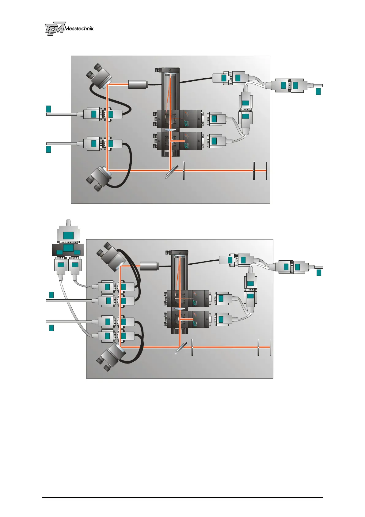
9.1.1 Cable Connections:
laser
PSD
A
PSD
B
PSD
1
PSD 4D 7.4
BeamLock 4D Series
®
digital
PSD B
PSD 4D 7.4
BeamLock 4D Series
®
digital
PSD A
laser
PSD
1
PSD
1
"PSD 1"
laser
PSD 4D
M1
M2
beam sampler
iris 1
"target"
iris 2
screen
to BLM / SPM
module
PSD
1
PSD
1
M1M2
M2
M2
M1
M1
to motor
driver
module
"M1"
"M2"
Plug'n Play Kit "Motorized"
Cabeling a motorized system
laser
PSD
A
PSD
B
PSD
1
PSD 4D 7.4
BeamLock 4D Series
®
digital
PSD B
PSD 4D 7.4
BeamLock 4D Series
®
digital
PSD A
laser
PSD
1
PSD
1
"PSD 1"
laser
PSD 4D
M1
M2
beam sampler
iris 1
"target"
iris 2
screen
to BLM / SPM
module
PSD
1
PSD
1
M1 A1
A2
A1
A2
A2
A2
A1
A1
piezo
actors
piezo
actors
M2
M2
M2
M1
M1
to motor
driver
module
to piezo driver module
"M1"
A2
A1
Plug'n Play Kit "MoPiA"
Connecting a MoPiA system
o Power Cord to Control Rack (Module "PowerBlock" at the rear)
o “USB” at front to USB connection of computer (use always the same USB port, to avoid
changing COM number at each connection)
(Alternatively you can use the RS232 serial interface at the rear, connected with a
standard 1:1 Sub-D9 cable)
o Connector “PSD 1” at rear Y-shaped adapter “PSD1” Detector: “PSD A” and
“PSD B”
o If the laser is supplied by the Aligna rack case (laser has a HD15 pole cable): Use
HD15 Y-Adapter for laser, and plug it in between one of the motor cables (M1, e.g.) or
in between the PSD cable. (All HD 15 plugs lead supply voltage at pins 6,7,8)